PLEXPERT Glossary

Terms and definitions in Plastic Industry

Cooling System

Logistic

Write the word that we shall describe to you

Terms

10 + 14 =


Do you want to hide this popup?

Cooling Channel

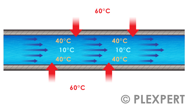
Through the melt, heat is introduced into the mold and it needs to be removed.
Therefore, holes are drilled into the mold. During the process, water or oil will flow through them. The holes themselves are called cooling channels.
For a high effectivity of a cooling channel, its distance to the cavity and to neighboring channels must be chosen wisely.
The length and diameter, as well as the curve angle in which cooling channels meet each other, influence the quality of the cooling.
The same is true for the temperature and the speed of the coolant.

Cooling Channel in Injection Molding

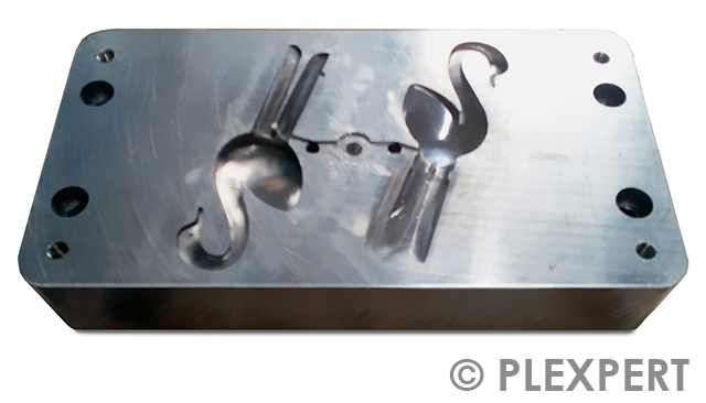
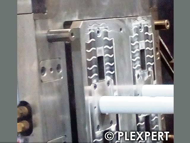
Cooling System: Adding a cooling channel into a mold plate.

Related topics:

Cooling System
Conventional Cooling
Reynolds-Number

This glossary of plastic industry is provided by PLEXPERT Canada Inc.

Bridge Crane

A motor-driven or manually driven unit which can move in more than two directions to deliver loads (horizontally or vertically) is referred to as a crane.
In terms of injection molding, the crane is usually mounted below the ceiling of the machine hall.
With the load hook of the crane, molds are transported from the provisioning area to the injection molding machine.
The use of the crane facilitates the set-up process by direct and safe positioning of the mold between the clamping plates of the injection molding machine.

Bridge Crane in Injection Molding

General: Bridge crane with a maximum load of 12.5 t (metric) in an injection molding company.

Related topics:

Footprint
Floor Load
Clamping Force

This glossary of plastic industry is provided by PLEXPERT Canada Inc.

Capacity planning

In order to efficiently utilize the available resources of a company, such as manpower, machines
and materials, and to achieve production targets, planning is required.
This is known as capacity planning or scheduling.
It is a crucial process in production and business management, as it avoids bottlenecks and ensures smooth process organization.
Today, planning is supported by appropriate software that manages the manpower, machines and materials, etc. and enables them to be included in capacity planning.
Capacity planning is part of work preparation.

Capacity planning in Plastic Industry by IKOffice

Example of capacity planning using software

Related topics:

Resource planning
ABC-Analysis
Test Plan


This information and services are provided by:

IKOffice logo


This glossary of plastic industry is provided by PLEXPERT Canada Inc.

Chinaplas

The International Exhibition on Plastics and Rubber industries in China, called Chinaplas, is an exhibition from the organizer Adsale.
In 1983, it opened the doors for the first time in Guangzhou (China).
Since 2006, it has been approved by UFI (The Global Association of the Exhibition Industry).
Chinaplas runs every year for four days and has a significant world wide influence on the plastics and rubber industries.
It is the biggest fair for this industry in Asia and is held in yearly turns in Guangzhou and Shanghai.

Chinaplas in Plastic Industry

General: Logo from Chinaplas fair

Related topics:

Fakuma
Moulding Expo
Interplastica

This glossary of plastic industry is provided by PLEXPERT Canada Inc.

CMYK

In the printing industry, a specific color model is used to represent the various colors that can be printed on paper or other materials. This model is based on the four primary colors of cyan, magenta, yellow, and black (key), which are mixed in different combinations to produce a wide range of colors.
This method is commonly used in the printing industry to reproduce precise and consistent colors. The acronym CMYK stands for these four colors and describes the subtractive color system, which contrasts with the additive RGB color system used for screens.

CMYK in Plastic Industry

General: Mixing of colors
General: Printer cartridges

Related Topics:

Masterbatch
Plastics Diagnostics
Quality

This glossary of plastic industry is provided by PLEXPERT Canada Inc.

Computer Aided Design (CAD)

The development of designs using a computer is called CAD (short for Computer Aided Design).
This includes all computer-aided activities in a design process.
There is a differentiation between 2D and 3D CAD systems according to the available software and the aim.
3D CAD systems can be differentiated into wireframe- surface- and solid modelling tools.
In common CAD systems a mixture of all of the discussed modules can be found.
The design is mostly done in 3D while a 2D drawing can be extracted based on the given model.
Typical data formats are Step (.stp or .step) to exchange models between CAD systems as well as STL (.stl) if it comes to simulation or rapid prototyping.

Computer Aided Design (CAD) in Plastic Industry

General: Display of a CAD user interface

Related topics:

CAM
CAE
CIM

This glossary of plastic industry is provided by PLEXPERT Canada Inc.

CoreTech System Co., Ltd.

is the name of a company that was founded 1995 to develop innovative simulation applications under the name of Moldex3D.
With highly educated software engineers, a clear vision and their own material laboratories, the company is now the leading supplier of true 3D injection molding software.
With more than 11 offices and a large network of re-seller plastic simulation is brought to the door step of the plastic industry all over the world.

CoreTech System Co., Ltd. in Injection Molding

CoreTech headquarter in Taiwan (Photo credit: CoreTech)

Related topics:

Mold filling phase
Packing phase
Warpage

This glossary of plastic industry is provided by PLEXPERT Canada Inc.

Dew Point

The air that we breath and around us is in general a mixture of gases with a certain level of humidity. This mix of humid gases may contain steam and air.
Steam may be exchanged by other condensable elements, air by specific gases.

The dew point is defined as the temperature of a humid gas in condition of equilibrium where condensation and vaporization is in balance. The gas is therefore just saturated.

The dew point of compressed air at 6 bar is -40 °C. This dew point should be used to avoid water in the pneumatic system and/or water drops on plastic parts, when blown off.
To assure an efficient drying of plastic resins, the used heated air should provide a dew point of 0 °C.

Dew Point in Injection Molding

The dew point in the phase diagram is situated on the yellow line between gaseous (gray) and liquid (purple) dependent on the respective pressure.

Related topics:

Material Drying
Compressed Air Dryer
Residual Moisture

This glossary of plastic industry is provided by PLEXPERT Canada Inc.

Dry Ice

Deposits, e.g. caused by outgassing of additives during the production of plastic parts, contaminate the surfaces of tools. This can lead to problems with venting, among other issues.
Effective and gentle cleaning of the surfaces of injection moulds can be achieved by using dry ice. This is produced from liquid carbon dioxide (CO2).
In a so-called pelletizer, the (compressed) liquid carbon dioxide is expanded under atmospheric pressure. This physical process produces dry ice snow. This is pressed through an extruder plate to produce round, hard dry ice pellets. These are elongated grains with a diameter of 3 mm.

Dry Ice in Plastic Industry by GWT

Dry ice after being in the pelletizer

Related topics:

Dry ice cleaning
Burn mark
Quality


This information and services are provided by:

GWT logo


This glossary of plastic industry is provided by PLEXPERT Canada Inc.

FAKUMA

On the grounds of the "Messe Friedrichshafen", the Fakuma takes place for two consecutive years. In the year of the K-Show the trade show for plastic processing Fakuma is suspended.
Founded in 1981 the Fakuma counts as one of the most important trade fairs in Germany and gains as well international significance.
This can be seen in the steadily rising numbers of exhibitors and visitors.
Exhibitors from more than 40 countries world wide show what is new in all sectors of the plastic industry.
Organizer of the Fakuma is the company P.E. Schall GmbH & Co. KG, which through its vision and commitment has made the fair a leading trade fair for the plastic industry.

FAKUMA in Plastic Industry

General: Fakuma company logo
 
Official website in English:

 
Related topics:

Chinaplas
Interplastica
Moulding Expo

This glossary of plastic industry is provided by PLEXPERT Canada Inc.

Floor Load

The maximum weight per square meter that can be taken by a floor without getting damaged is called floor load.
The technical design for a factory floor depends on mechanical and chemical needs.
The mechanical load for a floor is determined by the weight of the machines and shelves, trucking and forklift trucks, vibrations during production processes, and so on.
Chemical resistance is required in regard to zero emission, clean room needs, acid resistance, etc.
An architect needs to consider these requirements in planning and awarding the factory floor to comply with the building physics and production requirements.
Something important for the installation of an injection molding machine is the size of the machine feet over which the total weight is transmitted into the ground. In addition, the number of machine feet and their position to each other is significant as well.
Should the floor load be exceeded steel plates can be put below the feet for the machine to have a better weight distribution on the floor.

Floor Load in Plastic Industry

General: New floor with a maximum floor load of 1300 kg/m².

Related Topics:

Machine Center of Gravity
Footprint
Clamping Force

This glossary of plastic industry is provided by PLEXPERT Canada Inc.

Herschel

Friedrich Wilhelm Herschel was born in Hannover (Germany) in 1738 and died in Slough (England) in 1822.
Since 1770 he was engaged in building astronomical instruments and in 1781 he discovered the planet Uranus in our solar system.
In the course of time he created a catalog with more than 2500 entries of nebulous objects and double stars.
In search of materials with better optical properties, he discovered infrared radiation in 1800 by directing sunlight through a prism
and using a thermometer to detect a further rise in temperature behind the red end of the visible spectrum.
He concluded that some invisible form of energy must be operating there.
Today, we use infrared cameras to record the thermal radiation of plastic parts, for example, and use it to evaluate the quality of the manufactured parts.

Herschel in Injection Molding

Bust of Wilhelm Herschel

Related topics:

Infrared radiation
Emission
IR-ThermalSystem

This glossary of plastic industry is provided by PLEXPERT Canada Inc.

Infrared Radiation

Each object emits a certain amount of radiation depending on its temperature.
The radiation which adjoins the visible light in direction of larger wavelengths is called infrared or thermal radiation.
This type of radiation was discovered in 1800 by William Herschel.
The wavelength of the infrared radiation is in the range of 780 nano-meters to 1 millimeter.

Infrared Radiation in Plastic Industry

General: The area on the right side of the color bar is called infrared radiation.

Related Topics:

Infrared Camera
Emissivity
Herschel

This glossary of plastic industry is provided by PLEXPERT Canada Inc.

K Show (K)

The international trade fair for the plastic and rubber industry, called K-Show, takes place every three years since 1952.
More than 3000 exhibitors from more than 60 nations present their products and services during 8 days in Düsseldorf, Germany.
This makes the K-Show the worldwide largest trade fair for the plastic industry.
The products range from raw materials and auxiliaries, machinery and equipment, semi-finished products, technical parts and reinforced plastics to services regarding all other topics about plastic.

Other name: K trade show

K Show in Injection Molding

General: Logo of the K-Show.

Related topics:

ChinaPlas
Fakuma
Moulding Expo

This glossary of plastic industry is provided by PLEXPERT Canada Inc.

Kunststoffmesse24

Innovative ideas, products and services are still mainly presented at industry-specific trade fairs.
These fairs are organised in the region or supra-regionally.

In the past, trade fairs were used to request information about specific products from several manufacturers who were on site at the trade fair.

Today, this information must be available immediately.
Search engines on the Internet show many results for queries, which often have to be evaluated laboriously.

The Kunststoffmesse24.de platform has been set up to bundle industry-specific information and keep it permanently available.

This gives companies a further presence on the Internet with backlinks and marketing posts in the social media in addition to their homepage.

Access to Kunststoffmesse24 is permanently available around the clock.

Kunststoffmesse24 in Plastic Industry

General: Lobby Kunststoffmesse24
General: Kunststoffmesse24

Related Topics:

Chinaplas
Fakuma
Moulding Expo

This glossary of plastic industry is provided by PLEXPERT Canada Inc.

Manufacturing Execution System (MES)

This term refers to a software-based solution that supports companies in the manufacturing industry to efficiently plan,
control and monitor their production processes.
The software serves as a link between higher-level corporate planning and actual implementation at store floor level.
The MES is therefore the process-related level in a production management system. The term production control system is often used synonymously.

The real-time data visualized by the MES and functions for production tracking, quality assurance and resource management ensure optimal execution of the production processes.

Manufacturing Execution System (MES) in Plastic Industry by IKOffice

Example of the dashboard in a manufacturing execution system

Related topics:

Capacity planning
Machine Setup Sheet
Control Chart


This information and services are provided by:

IKOffice logo


This glossary of plastic industry is provided by PLEXPERT Canada Inc.

Moulding Expo

Since 2015, Moulding Expo has been a popular meeting place for the plastic industry.
The fair takes place every two years for four days in Stuttgart, Germany.
Tool, model and mold makers present themselves.
Additionally, systems and services for the plastic industry and metal processing are displayed.

Moulding Expo in Plastic Industry

General: Logo of the Moulding Expo

Related topics:

Fakuma
ChinaPlas
Interplastica

This glossary of plastic industry is provided by PLEXPERT Canada Inc.

Oil separator

In compressed-air systems, a dedicated separation unit removes oil aerosols and fine particles from the airflow. This ensures clean compressed air suitable for sensitive applications where even minimal oil content could cause quality or performance issues. The purification also protects downstream components from wear, thus extending their service life. Filtration and coalescence mechanisms collect and discharge oil droplets effectively. Overall, the device improves operational reliability and maintains stable process conditions.

Oil separator in Injection Molding

Oil separator on the rear wall of an injection molding machine

Related topics:

Compressed-air dryer
Evacuation
Conditioning

This glossary of plastic industry is provided by PLEXPERT Canada Inc.

Plastics Memo Challenge

Plastics Memo Challenge is the name of a game that is available for free download from the Android Play Store.
The game gets young people excited about plastics technology and imparts knowledge in a playful way.

In the game, digital cards are revealed with images of the injection molding process, extrusion, and so on.
For each pair found, information and details can be displayed through the direct link to the glossary.

The game was created with the support of PLEXPERT Studios.

Plastics Memo Challenge in Plastic Industry

General: Icon of the game after installation on a Android smart phone
General: Excerpt from the Youtube video for the game
https://www.youtube.com/watch?v=66pwBIznnp0

Related Topics:

PLEXPERT

This glossary of plastic industry is provided by PLEXPERT Canada Inc.

PLASTPOL

Kielce is one of many interesting locations in the heart of Poland.
And every year the city becomes the hub of plastics technology.
Over four days the Plastpol trade fair becomes the showcase for the most important plastics and rubber business-sector companies.
The trade fair has taken place annually since 1997 and is growing continuosly. 2022 more than 700 exhibitors from over 32 countries show what is trending in the plastic industry.
This is why the Plastpol is considered the leading event of the plastic industry in Central and Eastern Europe.

PLASTPOL in Injection Molding

General: Logo of the Plastpol

Related topics:

Chinaplas
Interplastica
Fakuma

This glossary of plastic industry is provided by PLEXPERT Canada Inc.

PLEXPERT

A group of experts in the plastic industry founded the company PLEXPERT, 2006 in Germany, in order to save resources, providing a positive impact on budget and environment.
There are two divisions within the company. One is focusing on finite element simulations (FEM) like injection molding simulation and structural analysis.
Based on decades of practical experience DFM conform results are given by the consultant service of PLEXPERT to decrease part costs and increase quality in the production of plastic parts.
The second division is focused on the development and supply of soft- and hardware to the plastic industry. With the state of the art products PLEXPERT contributes to secure production and reduce the need of precious resources.
Today PLEXPERT has offices in Canada, Germany, Thailand and China in order to support its customers fast and effectively.
Due to a close network of plastic experts, partners are available in many other countries as well and offer PLEXPERT products and services.

PLEXPERT in Plastic Industry

PLEXPERT Company Logo.

Related topics:

Injection Molding Simulation
Moldex3D
IR-ThermalSystem

This glossary of plastic industry is provided by PLEXPERT Canada Inc.

Spline

Even originally used to describe a long thin slat in shipbuilding, the term spline is nowadays used in connection with CAD systems.
In mathematics, a spline is a smooth curve, which runs through (or near) a series of points. These points (also called control points) influence the shape of the resulting spline curve.
If a spline curve can be described in all sections using a linear function, the spline is also called polygon or linear spline.
Similarly, square or cubic splines can be found.
In CAD systems mostly Non-Uniform Rational B-Splines (NURBS) are used for the representation of a curve. Based on spline curces spline surfaces can be created.
For them the term free-form surfaces is very often used. Free form surfaces are needed in particular in automotive engineering.

Spline in Plastic Industry by Spline-Konstruktionen

General: Spline curve with control points created in a CAD system

Related topics:

Computer Aided Design (CAD)
Computer Aided Manufacturing (CAM)
Surface Mesh


This information and services are provided by:

Spline-Konstruktionen logo


This glossary of plastic industry is provided by PLEXPERT Canada Inc.

Thinner

In printing processes, such as pad printing, an additional thinner (solvent) is added to the printing varnish. The addition of a thinner does not just influence the viscosity and ink dispensing behaviour of the pad printing ink from the pad to the workpiece, but it also has a very particular influence on the drying speed. By adding a thinner, the printing process can therefore be optimally adjusted to the specific local conditions.

Thinner in Injection Molding

A thinner to set the printing process regarding to the local conditions.

Related topics:

Mixing Ratio
Xscale
Additive

This glossary of plastic industry is provided by PLEXPERT Canada Inc.

Time tracking

Time Tracking refers to the systematic recording, documentation, and evaluation of employees’ working hours within a company. It includes the start and end times of work, breaks, as well as overtime, vacation, and sick leave. Modern electronic systems also enable project-based time tracking and resource management. It supports the optimization of operational processes, compliance with labor regulations, and transparent payroll accounting. Effective time tracking contributes significantly to cost control, productivity improvement, and employee motivation.

Time tracking in Plastic Industry

Modern time tracking device
Modern time tracking device in use

Related Topics:

Manufacturing data collection
Production planning
Human resource management

This glossary of plastic industry is provided by PLEXPERT Canada Inc.

Tripple Point

Substances exist in solid, liquid and vapor phase - the such a called thermodynamic phases. Under normal conditions, the phases transfer from solid to liquid to gas and the other way around.
At the tripple point a substance can exist in three different thermodynamic phases in parallel (e.g. solid, liquid and gas phase).
The phase diagram shows, that the phase boundaries meet at the tripple point.
Helium is the only known substance, which has no tripple point with solid/liquid and gas phase.
All other materials can exist in these three phases at the same time.

Water (H2O), same as other substances is present at the tripple point in solid, liquid and gas phase, also called the thermodynamic equilibrium.
Below the tripple point water changes its phase directly from gas to solid, also called frost point.

Tripple Point in Injection Molding

Phase diagram with the tripple point at the intersection between the phases solid (blue), liquid (purple) and gaseous (gray).

Related topics:

Compressed Air Dryer
Cooling System
Heat Exchanger

This glossary of plastic industry is provided by PLEXPERT Canada Inc.

TTY Interface (Teletypewriter)

A TTY interface (teletypewriter) provides a text-based communication channel between a user and a computer. Originally, the term referred to physical teleprinters connected via serial lines to send input and receive output. In modern Unix and Linux systems, TTY refers to virtual terminals that serve the same purpose—allowing users to input commands through the keyboard and display system output as text. These interfaces remain fundamental for command-line interaction, system administration, and automated processes, even in environments dominated by graphical user interfaces.

TTY Interface (Teletypewriter) in Injection Molding

Classic terminal with software for communication via TTY interface

Related topics:

Terminal
Shell
Command line

This glossary of plastic industry is provided by PLEXPERT Canada Inc.

Vibratory Bowl Feeder

All cylindrical sorting machines, which put parts on a given track and bring them into a specific position, are called vibratory bowl feeder.
The bowl, with unsorted small parts, is brought into vibration (mechanical or electromagnetic). These vibrations transport the parts on spiral lanes equipped with order systems to ensure that the parts will leave the bowl in a given position. Single vibrator bowl feeders can sort up to 30.000 parts per hour.
Due to the noise, it is advisable to use a noise insulating hood to reduce noise pollution.

Vibratory Bowl Feeder in Plastic Industry

General: Vibratory bowl feeder sorting sealing rings.

Related topics:

Insert
Part control
Sorting

This glossary of plastic industry is provided by PLEXPERT Canada Inc.

Filter Nozzle

Contamination (especially when using recyclates) can be removed from the plastic melt with the help of a filter nozzle.
This saves the often very complex cleaning of the following mold components.
Furthermore the plastic melt is homogenized by the filter nozzle.
This has highly positive effects for the distribution of additives and colorants.

The fitler nozzle is attached to the injection unit using a machine-dependent adapter.
The filter removes any contamination (e.g. metal or wood shavings, not melted material) from the plastic melt.

The filter nozzle is very flexible and can be used for almost every application, as well as for filled materials, due to the different filter fineness.
If the filter is contaminated, it can be flushed without disassembly by an automatic "flushing process".

Filter Nozzle in Plastic Industry by HFT

Hot Runner: Filter nozzle with two different filter inserts.

Related topics:

Cleaning Granulate
Hot Runner System
Masterbatch


This information and services are provided by:

HFT logo


This glossary of plastic industry is provided by PLEXPERT Canada Inc.

Heater Band

In hot runner systems heater bands are used. This is to bring the temperature inside of the melt channel up to the wanted process temperature and keep it constantly at this level.
The hot runner system consists mostly of one manifold and one or more hot runner drops.
In order to control the temperature a sensors are used in combination with PID-Controller.
The aim is to reach a homogeneous temperature distribution within the melt channel.

Heater band

Hot Runner: Multiple heater bands coil around the hot runner components.

Related Topics:

Hot Runner
Hot Runner Nozzle
Manifold

This glossary of plastic industry is provided by PLEXPERT Canada Inc.

Hot Runner

In an injection molding tool, the melt channel between cylinder and cold runner / cavity is called hot runner.
The difference from a cold runner is that the hot runner has at least one heater band to keep the hot runner at temperature.
The melt inside the hot runner stays fluid during the complete cycle and will be used directly for the next shot.
No waste is produced.
Hot runners are used to save material or to avoid weld lines (sequential injection).

Hot Runner in Plastic Industry
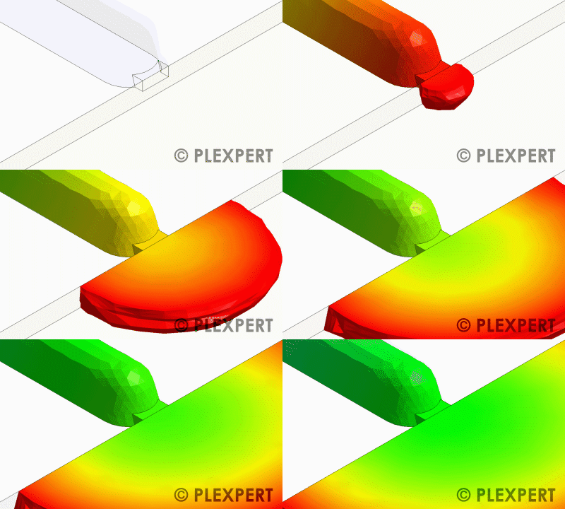
Image 1 - Hot Runner: The hot runner is a heated melt channel.
Image 2 - Hot Runner: Hot runner drop - From real to simulation

Related Topics:

Hot Runner System
Valve Gate
Manifold

This glossary of plastic industry is provided by PLEXPERT Canada Inc.

Hot Runner Nozzle

In a hot runner system, the hot runner nozzle is located between the manifold and cold runner or cavity.
As it is the last heated area for the melt, a good temperature control is important.
There are both, open and closed nozzles (valve gates).

hot runner nozzle

Hot runner regulator

This device is used for precise temperature control in hot runner systems of injection molds. By accurately regulating the heaters in the manifold and nozzles, it ensures a consistent melt temperature, which is essential for uniform cavity filling and avoiding quality deviations. Modern devices feature zone control, diagnostics, and overheating protection. Optimal temperature management reduces energy consumption and extends the service life of tool components.

Hot runner regulator in Injection Molding

Regler mit vier Regelzonen

Related topics:

Hot runner system
Injection mold
Temperature sensor

This glossary of plastic industry is provided by PLEXPERT Canada Inc.

Hot Runner System

The transportation of the molten plastic from the injection unit through the mold to the cavity can be done by a hot runner system.
This consists of at least one sprue bushing, the manifold and one or more hot runner gates.
The single components are provided with heaters, which are controlled by suitable PID-Controllers, to achieve a uniform temperature distribution. The system, on the other hand, is thermally decoupled from the mold so that there is a homogeneous heat balance inside the hot runner system.
Advantages of a hot runner system are for example the saving of material and the reduction of the cycle time.

There are different versions of hot runner systems.
The simpliest is the hot runner system with thermal lock.
At the end of the injection and packing phase the melt is cooling down at the gate due to the heat transfer in the colder mold.
The viscosity of the plastc decreases and a "thermal lock" develops, which prevents the melt from entering into the cavity.

Hot runner systems with valve gates are commonly used.
A needle is added to the gates. It can be moved by cylinders (hydraulic or pneumatic) allowing or preventing the melt to enter the cavity.
Advantages of the usage of valve gates are the controllable filling of the parts and that the break-off point can be designed without a residual pin.

Hot Runner System in Plastic Industry by HFT
Image 1:Hot runner: Hot runner system with thermal lock
Image 2:Hot runner: Hot runner system with valve gates

Related topics:

Hot Runner
Sequential Injection
Support


This information and services are provided by:

HFT logo


This glossary of plastic industry is provided by PLEXPERT Canada Inc.

Internal Valve Gate

Hot runner drops can be used with a needle inside. These hot runner drops are called valve gates.
However, the opening and closing of the needle can be done in different ways.
One way is to use air in order to move the needle and is implemented in the internal valve gate nozzle.
This pneumatic valve gated hot runner operates entirely without elastomeric seals, lubricants, or cylinder cooling.
It can operate at extreme temperatures of up to 400°C (750°F).

Internal Valve Gate in Plastic Industry by MHS

Image: Open and closing of the pneumatic hot runner nozzle.

Related topics:

Manifold
Hot Runner
Sequential Injection


This information and services are provided by:

MHS logo


This glossary of plastic industry is provided by PLEXPERT Canada Inc.

Manifold

The hot runner system can be separated in different components.
The area, where the melt is divided into the different hot runner gates, is called manifold.
For molds with multiple cavities, a homogeneous melt temperature and pressure distribution are necessary.
Therefore, the manifold should be preferably symmetrical.

Manifold

PID-Controller

If there is a hot runner system implemented in the mold a PID-Controller is used to bring the heater band up to a given temperature.
By controlling the heater band, the temperature at the sensor oscillates around the requested temperature.
Dependent on the choice of P-,I- and D-values reaching the given temperature happens faster or slower.

PID-Controller

Valve Gate

Nozzles in the hot runner system are divided into open and closed nozzles.
Closed nozzles can be opened and closed with the help of a steel needle, therefore the name valve gate.
The needle pushes the gate flat and only a single round mark is visible after closure of the gate.
The filling and packing phase can be influenced directly by the control of the needle.

Valve Gate

Black radiator

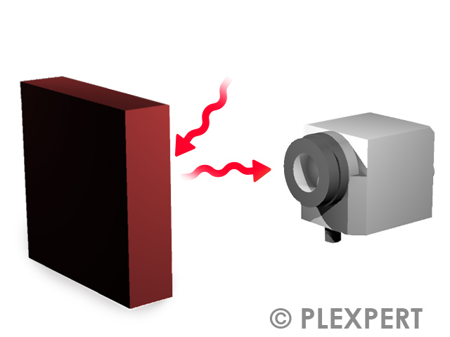
A body that is hit by radiation and absorbes it all, is called a black radiator.
This body has no losses due to reflection or transmission and emits the maximum possible energy in all directions equally.
For a defined waveband, the emitted radiation depends only on the temperature of the black radiator.
In reality one can not find a body that can emit 100% of a radiation.
The best possible reproduction is achieved with a cavity with matte black walls all having the same temperature.
A beam falling through a hole into the cavity is reflected and absorbed several times at the inner wall.
The radiation coming out of the hole corresponds to the temperature of the body.
This effect is used, e.g. in the calibration of IR measuring instruments.

Black radiator in Injection Molding

Infrared: Schematic structure of a black radiator

Related topics:

Emission
IR-Thermalsystem
Infrared radiation

This glossary of plastic industry is provided by PLEXPERT Canada Inc.

Emission

The ability of an object to emit infrared radiation is called emission.
In the infrared temperature measurement, the temperature of the object is calculated based on the intensity of the emitted radiation.
The proportion on emission of the radiation collected by a infrared camera is described by the emissivity.

Emission in Plastic Industry

Emissivity

The radiation detected by a thermal camera in a non-contact temperature measurement consists of the reflection, the transmission and the emission of infrared radiation emanating from objects in the field of view of the camera. The emissivity is a dimensionless measure that indicates the ratio of the emitted radiation of the measurement object in relation to the incident radiation.

Emissivity depends on the material, the surface texture and, in some cases, the temperature of a body. In general, the higher the emissivity of a body, the easier the temperature can be measured with a IR-camera.

The following relationship applies: Emissivity + Reflection + Transmission = 1

Emissivity in Injection Molding

Infrared: Emissivity of different materials (Concret = 0,95, Wood = 0,90, Plastic = 0,97)

Related topics:

Infrared radiation
Transmission
Reflection

This glossary of plastic industry is provided by PLEXPERT Canada Inc.

Infrared camera

The thermal radiation of objects is found behind the visible red spectrum of light.

This range is called the infrared wavelength range.

Infrared cameras are used to make the temperatures of the "thermal radiation" (wavelength between 1µm and 20µm) visible.

The camera consists of a lens, a spectral filter, the detector (sensor) and appropriate electronics for amplification, linearization and corresponding signal processing.
Infrared cameras are used in many areas, because they allow the measurement of difficult to access or moving objects with short measurement and response times.
During the measurement there is no influence on the object to be measured.

In the field of plastics technology, infrared cameras are used, for example, for testing and monitoring the injection molding process.

Infrared camera in Plastic Industry

Infrared camera for use in manufacturing

Related Topics:

IR-ThermalSystem
Herschel
Injection molding simulation

This glossary of plastic industry is provided by PLEXPERT Canada Inc.

Reflexion

The ability of an object to mirror infrared radiation is called reflexion.
The amount of the reflected radiation depends on the surface of a given object.
Plastics have usually a low amount, while shining metals (for example an insert in an injection mold) have a high amount of reflexion.
The higher the proportion of reflexion, the more difficult it is to measure temperature using an infrared camera.

Reflexion in Plastic Industry

Transmission

The movement of infrared radiation through an object is called transmission.
Most objects are impermeable to infrared radiation.
Therefore the proportion of transmission is usually set to zero, if the object is measured by an infrared camera.
Exceptions are thin plastic films. Here transmission occurs. An infrared measurement of a thin film usually shows the surface temperature of the underlying object and not the one from the film.

Transmission in Plastic Industry

Baffle

A uniform cooling of the part is important in the injection molding process in order to reduce shrinkage and warpage.
Especially in long and narrow areas, the cooling layout is often difficult.
This is because the space is insufficient to drill holes next to each other.
Therefore, when there is only enough space for one hole, it is recommended to use a baffle.
It is inserted into the hole and redirects the coolant from one side into the hole and out on the other side.

Baffle in Plastic Industry

Injection Molding: The baffle consists of a drilled hole with an inserted divider plate.

Related topics:

Bubbler

This glossary of plastic industry is provided by PLEXPERT Canada Inc.

Bubbler

A uniform cooling of the part is important in the injection molding process in order to reduce shrinkage and warpage.
Especially in long and narrow areas the cooling layout is often difficult.
The reason is insufficient space to drill holes next to each other.
When there is only enough space for one hole, it is recommended to use a bubbler.
A tube is inserted into the hole.
The coolant flows inside the tube to the end of the hole and back on the outside.

Bubbler

Injection Molding: The bubbler consists of a drilled hole with an inserted tube.
[/caption]

Related topics:

Baffle

This glossary of plastic industry is provided by PLEXPERT Canada Inc.

Cashew gate

If a gate shall not be visible while using a cold runner to fill the part, the melt can be delivered into the cavity by using a cashew gate (also known as banana gate or curved tunnel gate).
The curved design of the runner makes it possible to gate on the backside of a part.
As soon as the mold is open the gate will be separated automatically.
But it needs to be kept in mind that brittle materials or fiber filled materials will break during ejecting and a small piece of material will block the channel afterwards.
Before using a cashew gate the stroke of the ejector pin as well as the type of material must be checked thoroughly.

Cashew gate in Injection Molding

Injection mold: Gating through a cashew gate

Related topics:

Pin gate
Edge gate
Tunnel gate

This glossary of plastic industry is provided by PLEXPERT Canada Inc.

Cavity

The space between the two mold halves, which should be filled with melt, is called cavity.
The shrinkage of the material needs to be considered for the production of the cavity to get dimensionally accurate parts.
In the injection molding simulation, it is important to use the cavity size for the warpage calculation.

cavity

Injection Molding: Half of the cavities visible in the ejection side of the mold.

Related Topics:

Parting Line
Shrinkage
Injection Side

This glossary of plastic industry is provided by PLEXPERT Canada Inc.

Cavity Count

An injection mold can contain one or more cavities.
The number of cavities is often named cavity count.
In general it is considered that all the cavities are identical if we talk about cavity count.
The more cavities in one mold, the more parts can be produced at once.
Therefore production time and part costs can be reduced.

Cavity Count in Injection Molding

Injection Mold: Multi-Cavity Mold with a Cavity Count of 4.

Related topics:

Multi-Cavity Mold
Stack Mold

<

This glossary of plastic industry is provided by PLEXPERT Canada Inc.

Cold Runner

The unheated melt channel from machine nozzle / hot runner up to the cavity is called cold runner.
In the injection molding cycle the cold runner is cooling down and freezes.
The gate geometry is very flexible, like umbrella gate, cashew gate, ring gate.
The cold runner is ejected together with the part.
The separation from the part is done automatically or manually.
The collected cold runners will be recycled or disposed as waste.

Cold Runner in Plastic Industry
Image 1: Injection Molding: A cold runner with a cashew gate is connected to a simple ring cavity.
Image 2: Injection Molding: Cold runner connected to parts (left) and same cold runner without parts connected

Related Topics:

Cavity
Jetting
Hot Runner

This glossary of plastic industry is provided by PLEXPERT Canada Inc.

Conformal Cooling

For complex parts, conventional cooling is not sufficient enough to achieve a uniform heat dissipation.
Here it is necessary to build the cooling system close to contour along the cavity.
This can be done by laser cusing and high temperature brazing.
These technologies allow to realize a good cooling system even in tight areas.
Conformal Cooling results generally in a reduction of cycle time and warpage.

Conformal Cooling in Plastic Industry

Injection Molding: This mold insert contains the conformal cooling.

Related topics:

Conventional Cooling
Baffle
Bubbler

This glossary of plastic industry is provided by PLEXPERT Canada Inc.

Conventional Cooling

The cooling system in the injection mold is usually inserted into the steel by drilling.
By adding plugs the flow path for the coolant is clearly defined.
The conventional cooling is cheap compared to other cooling technologies and for most molds satisfying.

Conventional Cooling in Plastic Industry

Injection Molding: This mold insert contains a conventional cooling, in which later a baffle is inserted.

Related topics:

Conformal cooling
Baffle
Bubbler

This glossary of plastic industry is provided by PLEXPERT Canada Inc.

Cooling System

The injection mold is brought up to a specific temperature by the cooling system, which consists of the cooling device and the cooling channels.
Water or oil is used as a coolant flowing through the channels.
The better the temperature layout, the shorter the cooling time.
The aim is a uniform temperature at the cavity wall.
This way one factor for the warpage can be reduced.

Cooling System in Plastic Industry

Injection Molding: The cooling system contains all cooling channels of the mold.

Related topics:

Baffle
Bubbler
Conventional cooling
Conformal cooling

This glossary of plastic industry is provided by PLEXPERT Canada Inc.

Edge Gate

One of the most basic gates for injection molding is the edge gate.
The gate normally has a rectangular cross-section along the parting line of the mold to connect the runner system with the mold cavity.
The common edge gate is positioned on the side of the cavity.
It can be easily manufactured by a basic machining process such as milling.
The disadvantage of the edge gate is the remaining of the connection of the molded part to the runner after ejection.
Additional mechanical action is needed for separation. Furthermore jetting might occur with this kind of gate.

Edge Gate in Injection Molding

Injection mold: A common edge gate is filling the part from the side

Related topics:

Lapped Edge Gate
Tunnel Gate
Banana Gate

This glossary of plastic industry is provided by PLEXPERT Canada Inc.

Ejection Side

A mold is usually divided into two sides according to their function.
The side with the ejector pins is called ejection side.
This side is moved for mold opening, therefore another common name is "movable side".

Ejection Side in Plastic Industry

Injection Molding: The green components belong to the ejection side of the mold.

Related topics:

Injection side

This glossary of plastic industry is provided by PLEXPERT Canada Inc.

Ejector

To get the parts homogeneously and with as least as possible tension out of the cavity, ejectors are used.
Additional ejectors can be set as optimization for the venting system.
The ejectors are mainly axial pins, which are located on the ejector plate and fixed from the ejector holding plate.
The movement of the ejector plate takes place most of the time by hydraulic.
When moving forward, the pins press against the parts and throw them out. The backwards movement is done by hydraulic or spring force.
The movement of the ejectors has a big influence on the wear of the mold.

ejector

Fan Gate

With this gate design, the plastic melt is introduced into the molded part through a widely spread cross section, allowing the flow front to expand more uniformly across a larger part width. This geometry forms the characteristic fan gate, which is particularly used for flat or thin-walled injection molded parts. The broad outlet area can reduce local shear peaks, weld lines, and visible flow marks. Width, thickness, and the transition to the part must be carefully designed because they influence pressure loss, filling behavior, part stress, and subsequent gate removal. After injection molding, the gate is usually mechanically separated from the part.

Fan Gate in Injection Molding

Injection molding: Filling the cavity via a fan gate

Related topics:

Gate
Film Gate
Flow Front

This glossary of plastic industry is provided by PLEXPERT Canada Inc.

Fixed Side

A mold is usually divided into two sides according to their function.
The side, which is not moving during production is called fixed side.
This side contains the runner system, therefore another common name is "injection side".

Fixed Side in Plastic Industry

Injection Molding: The pink components belong to the fixed side of the mold.

Related topics:

Movable side

This glossary of plastic industry is provided by PLEXPERT Canada Inc.

Foam Injection Molding

A process where a physical or chemical blowing agent is solved into the polymer melt, which leads to the melt foaming and expanding in the cavity.
Due to the gas expansion of the blowing agent, the injected part will have a sandwich structure with a foamed core and compact skin layers.
The gas pressure inside the part can shorten or completely substitute the holding phase of the injection process, which leads to shorter cycle times.

With this process, part properties such as lesser warpage as well as part weight reduction can be realized. With process-optimized part design, part weight reductions and material savings of up to 35% have been realized.

Chemical blowing agents are usually added to plastics as a masterbatch and decompose into blowing gases and solid by-products under heat.
For the metering and mixing of physical blowing agents, such as nitrogen or carbon dioxide, additional equipment and a special screw are required.

Foam Injection Molding in Plastic Industry by Yizumi Germany GmbH

Injection Molding: Schematic plasticizing unit with special equipment for the introduction of physical blowing agents for foam injection molding (© Yizumi Germany GmbH)

Related topics:

Warpage
Material Drying
Cavity Pressure


This information and services are provided by:

Yizumi Germany GmbH logo


This glossary of plastic industry is provided by PLEXPERT Canada Inc.

Guide Pillar

A standard injection mold is split into the injection side and the ejection side.
When the mold is closing, the two halves of the mold are centered through the guide pillars.
In most cases, the guide pillars are fixed on the injection side.
The ejection side moves along with the guide pillars till the mold is completely closed.
In order to make the movement of the other half of the mold easier, guide pillars can have oil grooves.
Depending on the mold layout, guide pillars can have a centering collar to increase stability.
Four guide pillars will be used in one mold.
It has to be noted that the diameter of the guide pillars varies.
Three of them have the same diameter, one of them has a different one.
This is to make sure the mold cannot be mounted in the wrong way.

Guide Pillar in Plastic Industry

Injection Molding: Guide pillar without centering collar left, with collar right.

Related topics:

Mold Design
Mold Plate
Fixed Side

This glossary of plastic industry is provided by PLEXPERT Canada Inc.

Heat Transfer Coefficient

In the mold, the correct temperature transfer between different materials is of crucial importance. The heat transfer inside the mold depends on a material depended-value, the heat transfer coefficient. The higher it is, the better is the transfer of the thermal energy from one material into the next one. As the hot runner system should transfer as little heat as possible to the remaining mold, an air gap helps to receive a small heat transfer coefficient, to get an isolated system.
It is necessary to know, that the heat transfer coefficient is no a constant value. It depends on material specific properties, like specific heat capacity, density and thermal conductivity, as well as geometry and roughness of the surface and for moving fluids on the flow behavior.

Heat Transfer Coefficient

Hot Runner Support

In the injection mold, the hot runner system is thermally isolated with the help of the air gap.
Due to the acting forces it is necessary to use supports of the hot runner system as connection to the surrounding wall of the mold.
To get a preferably low heat lot, Titanium or ceramic is used as material for the support.
Furthermore, the aim is to keep the support as small as possible, but as big as necessary.

Hot Runner Support in Plastic Industry

Injection Side

A mold is usually divided into two sides according to their function.
The side with the runner system is called injection side.
This side is not moved, therefore another common name is "fixed side".

Injection Side in Plastic Industry

Injection Molding: The pink components belong to the injection side of the mold.

Related topics:

Ejection side

This glossary of plastic industry is provided by PLEXPERT Canada Inc.

Inking

To check if the parting line of the injection molding mold fit properly on each other inking is used.
This is done by applying inking-colour to one side of the mold (by spraying or brushing).
By closing and reopening the mold the colour is transferred to the other side of the mold.
Now it is easy to see where the mold fits exactly and where it does not.
This is an important information when it comes to subjects like short shot, flash formation or even multi-component molding.

Inking in Injection Molding

The inking colour shows where the parting line fits properly on each other and where not.

Related topics:

Quality
Burn Mark
Mold Breathing

This glossary of plastic industry is provided by PLEXPERT Canada Inc.

IR-ThermalSystem

Temperature plays the most important role if it comes to injection molding.
Before the part is ejected it is good practice to analyse the temperature distribution on the surface.
This is where IR-ThermalSystem comes into play.
It consists of an infrared camera, a magnetic stand, cables some electronic device and a specialized software (called IRDAS), that records
all the critical information from one shot to another.
The system used for quality control, supports a centralized database and can be connected to several other
products that are useful in the injection molding process.
This includes DiagBes as well as Xscale and Xmold.
Evaluating temperature helps to identify short shot and flashing as well as proper functionining of the cooling channels.

IR-ThermalSystem in Plastic Industry

Injection molding process: Camera on top of a mold as part of IR-ThermalSystem
Injection molding process: IRDAS-Software specialized for the IR-ThermalSystem

Related Topics:

Emission
Infrared Radiation
Control Chart

This glossary of plastic industry is provided by PLEXPERT Canada Inc.

L to D ratio

The length of the screw is specified exclusively in relation to the screw diameter.
Doing it like that allows to compare different screws much better.
The process-engineering effective length of the screw is specified as L.
This value represents the distance the granules/melt travels along the screw.
For the determination, the length from the front edge of the hopper to the backflow barrier is always used.
The effective length is set in relation to the diameter D of the screw.

L to D ratio in Injection Molding

Injection molding: Display of the L/D ratio on a screw

Related topics:

Injection molding
Cleaning granulate
Cavity pressure

This glossary of plastic industry is provided by PLEXPERT Canada Inc.

Mold

For the production of injection molded parts a mold is necessary to be placed on the injection molding machine.
It is commonly build out of steel or aluminum and is designed as a permanent form.
Depending on the plastic material used millions of parts can be created with one mold.
The complexity of a mold range from a simple two-plate molds up to a complex stack mold with sliders, etc.
To avoid additional costs it is important to think about the mold concept early in the concept phase of part design.

Mold in Injection Molding

Injection mold: 15 year old and more than 750000 parts produced.

Related topics:

Injection side
Ejection Side
Guide Pillar

This glossary of plastic industry is provided by PLEXPERT Canada Inc.

Mold Breathing

In injection molding, during filling and packing phase the two mold halves are hold closed with the clamping force against the pressure of the melt. If the driving force of the cavity pressure is higher than the clamping force, the mold is pushed open by a few thousandths to hundreds of millimeters. This is known as the so-called mold breathing. Too large mold breathing can lead to flash formation, while too low mold breathing results to air compression with burn marks.
In order to optimize the required clamping force, dial gauges can be attached to the mold to determine the mold breathing. Permissible respiration depends on the quality requirements of the injection molded part, the material and the size of the machine.

Mold Breathing in Plastic Industry

Injection Mold: Determination of mold breathing by means of a dial gauge.

Related topics:

Venting
Parting Line
Quality

This glossary of plastic industry is provided by PLEXPERT Canada Inc.

Mold plate

Plates, which contain the part-cavity in the injection mold are called mold plates.
Usually there is one mold plate for the injection side and one for the ejection side.
Dependent on the complexity of the part, the cavity is carved directly into the mold plate or embeded with inserts into the mold plate.
The primary cooling system of the cavity is located in the mold plates as well.

Mold plate in Injection Molding

Injection molding: CAD-data of the mold plates from the Certespiri mask

Related topics:

Cavity Count
Stack Mold
Slider

This glossary of plastic industry is provided by PLEXPERT Canada Inc.

Movable Side

A mold is usually divided into two sides according to their function.
The side which is moved for mold opening is called movable side.
This side contains the ejector pins, therefore another common name is "ejection side".

Movable Side in Plastic Industry

Injection Molding: The green components belong to the movable side of the mold.

Related topics:

Fixed side

This glossary of plastic industry is provided by PLEXPERT Canada Inc.

Part

"Parts, which have been produced from melt by non-cutting molding (e.g. by pressing, compression molding or injection molding) in all side closed molds" are referred
to as molded parts according to DIN 7708, sheet 1 [freely translated].
Thus in injection molding, the end product, which is produced by filling the cavity with molten plastic, is called a molded part.
It should be noted that a possibly existing cold runner is not a component of the molded part.

Part in Injection Molding

Injection molding: A horse as game character - generated through injection molding.

Related topics:

Quality
Warpage
Filling Study

This glossary of plastic industry is provided by PLEXPERT Canada Inc.

Parting Line

An injection mold consists in general of two halves: injection side and ejection side.
The touching faces between these two halves are called parting line.
Through this, the air is transported from the cavity to the outside.
When the mold is opened, part and cold runner are separated from the mold at this line and ejected.
The parting line emerges in general as a surrounding seam on the part.

Parting Line

Pin gate

If a cold runner is used to gate directly on a part, there is only one way to separate runner and part automatically.
This is by using a pin gate.
The mold needs to have 3 plates in this case and will get more complex.
During design phase of a pin gate it needs to be kept in mind to have the gate height between 0,5mm to 1mm and the gate diameter in between 40%to 80% of the part wall thickness.
This is to make sure the automatic separation will work properly during mold open.

Pin gate in Injection Molding

Injection mold: Filling of a cavity using a pin gate

Related topics:

Tunnel gate
Edge gate
Overlapping edge gate

This glossary of plastic industry is provided by PLEXPERT Canada Inc.

Plug

In injection molds with conventional cooling, the cooling system is manufactured with as little as possible drill holes.
A change in direction is realized by intersecting drill holes.
These auxiliary holes need to be closed by a plug to avoid the coolant flowing out of the mold.
Additionally plugs need to be inserted to define a clear direction of the coolant stream.
This way the coolant can flow through a drill hole in multiple areas.
The plugs prevent the coolant to flow into uncertain directions and support with the enforced flow direction a good cooling system of the mold.

Plugs in Plastic Industry

Injection Molding: Plugs to be inserted into the drill holes in the mold.

Related topics:

Variotherm
Baffle
Bubbler

This glossary of plastic industry is provided by PLEXPERT Canada Inc.

Pressure Distribution

The pressure at different positions inside the cavity/runner is called “Pressure Distribution”.
Ideally in injection molding process, the pressure distribution should be uniform throughout the cavity after the molten plastic completely fills the cavity. In this case the molded part shrinks uniformly.
In reality due to the different cooling behaviour of the part there is always a difference in pressure distribution.

Injection molding simulation is a great tool to predict the pressure inside the cavity, which can help to achieve uniform pressure distribution as good as possible.

Pressure Distribution in Plastic Industry

Injection molding: Pressure distribution inside the cavity at the end of filling phase
Injection molding: Pressure distribution inside the cavity in packing phase

Related Topics:

Injection Pressure
Cavity Pressure
Shrinkage

This glossary of plastic industry is provided by PLEXPERT Canada Inc.

Rating Plate

After an injection mold is finished it will get its rating plate.
There is no design of the rating plate generally admitted.
Very often rating plates are created based on factory standards and provided to the mold maker by the future owner of a mold.
There are different online portals available, where rating plates for injection molds can be ordered.
The most common entries are asked for in standard forms.

Often a D&B D-U-N-S® number is requested on the plate besides the name of the mold, the manufacturing date, the size of the mold and its weight.
This number is specific for a given supplier and is used to prevent unjustified passing of the tools to third parties.
The extent to which CE marking is required for tools has not yet been conclusively clarified.
It has to be noted that type plates have to be fixed on the mold and shall not be removable in order to secure the ownership of the mold.

Rating Plate in Plastic Industry by HS Formtechnik

Injection Molding: Two different rating plates on one mold

Related topics:

Stack Mold
Guide Pillar
Locating Ring


This information and services are provided by:

HS Formtechnik logo


This glossary of plastic industry is provided by PLEXPERT Canada Inc.

Runner system

All melt channels together are called runner or runner system.
For these names, there is no distinction between hot and cold runner.
A good runner is responsible for a balanced filling of the cavity and less material and pressure loss.

Runner system in Injection Molding

The runner system can contain a combination of hot and cold runner or only one of the two components.

Related topics:

Hot Runner
Manifold
Gate Position

This glossary of plastic industry is provided by PLEXPERT Canada Inc.

Slider

One parting line is not enough to eject complex geometries of injection molded parts.
Undercuts in the direction of ejection are the main difficulty.
So called slider are used to build an additional parting line.
The movement of the slider diagonally to the opening direction of the mold frees the undercuts and allows the ejection of the part.
Slider can be placed inside the fixed as well as the movable side of the mold.
The angle of the slider compared to the other parts of the mold should be between 83° and 97° to avoid a blocking of the slider.
The buoyancy inside the mold needs to be considered for the correct size of the slider.
It need to be ensured that the sliders are adequately locked.

Slider in Injection Molding

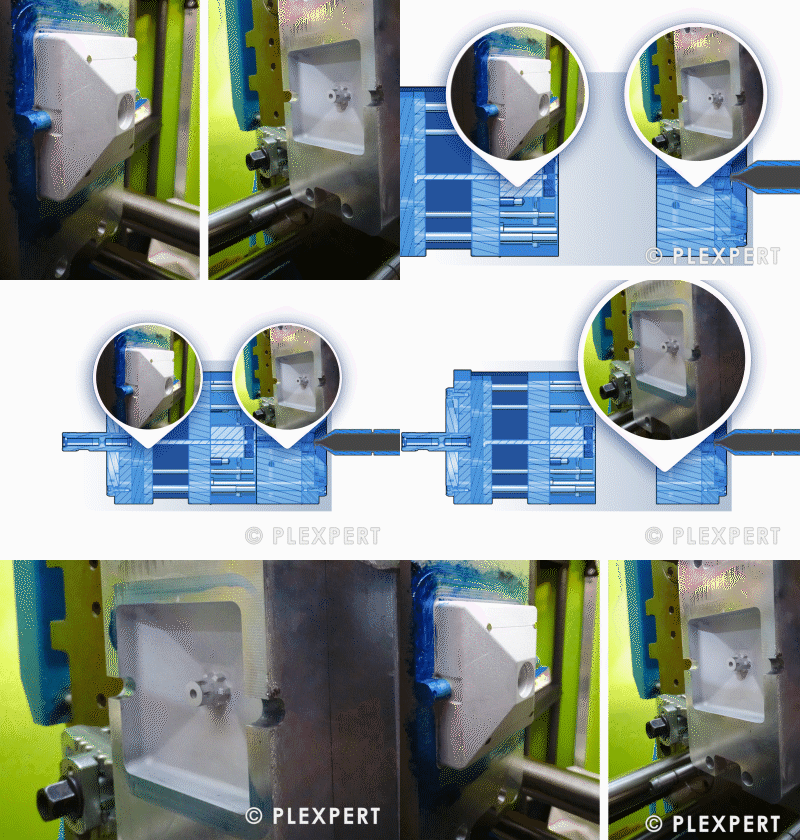
Opening of a simple mold with sliders

Related topics:

Opening Stroke
Clamping Force
Platen

This glossary of plastic industry is provided by PLEXPERT Canada Inc.

Soft Component

In the two shot molding, the second component is commonly soft and elastic.
Therefore, it is also called soft component.
Due to its flexibility, the influence of the soft component on the warpage of the part is very low.
Seals are frequently made as soft component by the two shot molding.
Moreover, TPE is typically used for soft components.

Soft Component in Plastic Industry

Injection Molding: The blue, soft component of the toothbrush is made of TPE.[/caption]

Related topics:

Hard Component
Overmolding
Secondary Injection Unit

This glossary of plastic industry is provided by PLEXPERT Canada Inc.

Sprue Bushing

In the injection molding process, the melt is guided from the machine nozzle into the sprue bushing and further into the runner system or the cavity.
The machine nozzle is pressed against the sprue bushing. In order to avoid leakage it is important that the radii of the machine nozzle and the sprue bushing are the same.
Sprue bushings are available with no radius, a radius of 15,5 mm or 40,0 mm.
The sprue bushing needs to be fixed against rotation, if a contour giving area has been incorporated. This can be done by flattening a side or inserting a pin.

Sprue Bushing in Plastic Industry

Tempering

In the plastics industry, a specific heat treatment process is essential to improve the performance and quality of injection-molded components.
This process, which is applied after injection molding, involves carefully heating the plastic parts to a precise temperature,
followed by a controlled cooling process.
The aim is to relieve internal stresses within the parts that can arise during the injection molding process.
This treatment not only improves the physical properties of the plastic products, such as flexibility and impact resistance,
but also increases their resistance to environmental influences and mechanical stresses.
The result is a significant increase in product quality and durability, which is beneficial for manufacturers and end users alike.

Tempering in Injection Molding

Injection molding: Heating cabinet - tempering molded parts over a certain period of time at a set temperature

Related topics:

Compressed Air Dryer
Industrial Robot
LSR Dosing Unit

This glossary of plastic industry is provided by PLEXPERT Canada Inc.

Tunnel gate

If a cold runner is used and an automated separation between part and runner is wanted, a tunnel gate can be used.
In this case the gate will be on the side of the part or a rib.
The tappered shape leads to a small gate size on the part surface and allows a good removal of the cold runner during mold open.
A baffle wall at the end of the tunnel is used to collect cold melt at the start of injection.
The separation between runner and part is possible by using a standard two plate mold.
Often there is a positive impact to the parts appearance due to the less visible gate on the side of the part.

Tunnel gate in Injection Molding

Injection mold: Using a tunnel to fill the part

Related topics:

Pin gate
Overlapping edge gate
Cashew gate

This glossary of plastic industry is provided by PLEXPERT Canada Inc.

Venting

The cavity contains air, which is pushed out by the arriving melt.
Therefore, venting is necessary to allow the air to escape the cavity.
Otherwise a compression of the air occurs, which leads to a rise of the temperature (burn mark).
The venting consists of small gaps, which are situated for example at the parting line, at the sliders and at the ejector pins.
Depending on the used polymer, the height of the gap needs to be adjusted.
If the gap is too small, it prevents the air from escaping.
If the gap is too big, flash formation occurs at the part.

Venting in Plastic Industry

Air Trap

In injection molding it may happen, that the air can't escape or that it moves only very slowly out of the cavity.
An air trap will occur if the air is surrounded by the melt completely or if it is at the end of the flowpath (missing or insufficient venting). Therefore, in this situation burn marks may occur.
The air trap can be located in the inside or at the surface of the part.
The later causes an incomplete filling.
With a good venting system and a mainly uniform wall thickness, air traps can be avoided.

Air Trap in Plastic Industry

Related topics:

Weld Line
Sink Mark
Void

This glossary of plastic industry is provided by PLEXPERT Canada Inc.

Burn Mark

If the air can't escape, it will be compressed by the melt.
This leads to an increase in temperature and builds burn marks (black marks on the polymer).
A better venting or slower injection at lower temperatures can solve this issue in most cases.

Burn Mark in Plastic Industry

Injection Molding Error: A burn mark at the end of the flow front

Related topics:

Air Trap
Weld Line

This glossary of plastic industry is provided by PLEXPERT Canada Inc.

Flash Formation

The pressure of the melt pushes the mold to open due to a too low clamp force.
On the parting line, the mold opens a little and the outcoming melt freezes and a flash remains.
The risk of the flash formation can be reduced by the use of a machine with a higher clamp force or the reduction of the specific pressure in the cavity.
Another reason for flash formation can be the wrong positioning of the touching surfaces at the parting line.

Flash Formation in Injection Molding

Injection molding defect: At the touching surfaces on the parting line it comes to flash formation.

Related topics:

Venting
Cavity Pressure
Movable Side

This glossary of plastic industry is provided by PLEXPERT Canada Inc.

Hesitation

In injection molding, the hesitation is one of the situations where molten plastic flows inside cavity with different velocities at the front as a result of different resistance to flow. At a region with higher resistance, the melt front tends to stagnate and slows down. The causes can be high variations in wall thickness and locally low mold wall temperature. The hesitation could lead to molding defects such as short shot, burn mark, air trap and poor part surface.
In perspectives of part and mold designs, the hesitation can be avoided by uniform wall thickness and cooling layout. On the other hand, higher melt temperature, higher mold temperature, and higher injection speed could ease the hesitation during the production.

Hesitation in Plastic Industry

Injection Molding Defect: Mold halves are not centered to each other leading to non-uniform wall thickness and hesitation effect subsequently.
Injection Molding Defect: At narrow lines of the filling contour hesitations occur.

Related Topics:

Filling Study
Gate Position
Core Shift

This glossary of plastic industry is provided by PLEXPERT Canada Inc.

Jetting

When the material enters a larger cavity with a high flow rate jetting might occur.
While the melt doesn't hit a wall, a snake-like cord is build until a wall is reached.
The cooling down of the cord surface prevents a good merging between the cord and the new entering melt.
This leads to a reduction of the stiffness and a visible mark.
Slow injection or a bulging wall directly behind the gate will prevent the jetting effect.

Jetting in Plastic Industry

Injection Molding Error: Jetting visible due to polarized light.

Related topics:

Shear Rate
Melt Front
Injection Time

This glossary of plastic industry is provided by PLEXPERT Canada Inc.

Sink Mark

In areas with thick walls and across from ribs, a hollow at the surface might appear.
Sometimes a difference in the gloss to the surrounding surface might be noticed only.
Mass accumulation leads to a higher volumetric shrinkage, which is insufficiently reached by packing pressure.
The surface is pulled to the inside during cooling and a sink mark appears.
Small wall thickness and higher packing pressure in the critical area reduce the risk of sink marks.

Sink Mark in Plastic Industry

Injection Molding Error (Image 1): The wing on this piece shows a sink mark.
Injection Molding Error (Image 2): Sink marks due to low packing pressure.

Related topics:

Void
Air Trap
Weld Line

This glossary of plastic industry is provided by PLEXPERT Canada Inc.

Thermal Impact

Heat can be described physically as oscillation of the molecules.
An excessive oscillation can impact the molecules of plastic drastically.
The effect of it is called thermal impact.
In the worst case, the molecules can break: the molecules degrade.
This is a damage of the plastic, which increases the higher the prevailing temperature.
Furthermore, the duration of the temperature effect - in injection molding called residence time - plays an important role.
An example from the daily life is the sunburn.
Here again, the two factors temperature and residence time are responsible for the thermal impact.

Thermal Impact in Plastic Industry by STAK

Injection Molding Defect: The longer and the higher the thermal impact of a body, the darker it will get (Example: Vegetable).

Related topics:

Burn Mark
Temperature
Shear Rate


This information and information services are provided by:

STAK logo


This glossary of plastic industry is provided by PLEXPERT Canada Inc.

Void

In areas with thick walls and across from ribs, a "hole" in the inside might appear.
Mass accumulation leads to a higher volumetric shrinkage, which is not insufficiently adjusted by packing pressure.
The melt is pulled to the surface during cooling, that a hollow remains in the inside.
CT-Scan and cutting the part help to detect these errors.
Small wall thickness and higher packing pressure in the critical area reduce the risk of voids.

Void in Plastic Industry

Weld Line

When at least two melt fronts meet, a weld line occurs.
Weld lines display on one hand a reduction of the mechanical strength, on the other hand a beauty error in the part.
The lower the melt front temperatures, the more difficult it is for the melt fronts to merge.
The smaller the meeting angle (melt fronts meet head-on), the more critical.
For fiber filled materials, a weld line changes the orientation of the fibers, that they will orient perpendicular to the flow direction.
To reduce weld lines it is possible to work with sequential injection or overflow cavities.

Weld Line in Plastic Industry

Injection Molding Error: Weld line with narrow meeting angle.

Related topics:

Air Trap
Gate Position
Temperature

This glossary of plastic industry is provided by PLEXPERT Canada Inc.

Backpressure

During plasticising in injection molding process, the melt is pushed forward by the rotating screw.
The pressure that is build up in front of the screw (P1) is responsible for her backward movement.
Backpressure (P2) is needed to withstand this backwards movement of the screw for a certain time.
This is to ensure a better mixing of color and additive, better melt uniformity, and controlling shot volume.
In the process shear heat is applied to the melt as well.
A recommended range of backpressure for most plastic materials range from 20 bar to 200 bar.
PVC on the other side uses backpressures of up to 400 bar.

Backpressure in Injection Molding

Injection Molding Machine: The backpressure counteracts against the backwards movement of the screw during plasticising.

Related topics:

Injection Pressure
Hopper
Screw Speed

This glossary of plastic industry is provided by PLEXPERT Canada Inc.

Clamping Force

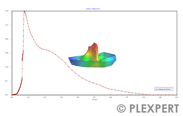
The machine is pressing the mold halves against each other to counteract the pressure of the melt in injection and packing phase.
The needed force for this is called clamp force.
Most injection molding machines contain this value in their name.
The unit might be displayed in kN or t.
If the clamping force is too low, the mold halves will be pushed away from each other by the melt and flash appears.
The injection molding simulation helps to determine the necessary clamp force in advance to choose a machine with the correct size.
The clamp force can be estimated by multiplying the projected surface with the cavity pressure.

Clamp Force in Plastic Industry

Injection Molding Machine: The curve of the clamp force helps to choose the correct machine size.

Related topics:

Ejection Side
Injection Side
Venting

This glossary of plastic industry is provided by PLEXPERT Canada Inc.

Columnless Injection Molding Machine

The clamping unit of an injection molding machine is typically guided on columns. However, columnless injection molding machines are also available on the market. The clamping force is applied over a C- or H-shaped frame. The big advantage of the columnless design is the very good accessibility for mold installation and handling. In comparison to the column-guided clamping unit, the entire surface of the platens can be used to mount the mold.

Columnless Injection Molding Machine in Plastic Industry

Injection molding machine: A movable platen of a columnless injection molding machine.

Related Topics:

Setting up
Bridge Crane
Mounting Clutch

This glossary of plastic industry is provided by PLEXPERT Canada Inc.

Dosing

The process in which plastic granulate is melted in the plasticizing unit and prepared in the required amount for the next injection cycle is called dosing.
During this process, the screw conveys the material forward while it melts through friction and external heating. The screw moves back axially, forming a defined melt cushion. A non-return valve prevents the material from flowing back into the rear section of the screw. The dosing amount is precisely controlled to ensure consistent cavity filling and reproducible part quality. Factors such as temperature, screw speed, and back pressure influence the dosing process and, consequently, the melt quality. Accurate dosing is crucial for the efficiency and quality of the injection molding process.

Dosing in Injection Molding

Injection molding machine: Schematic representation of the dosing process

Related topics:

2 Shot Molding
Injection Time
Filter Nozzle

This glossary of plastic industry is provided by PLEXPERT Canada Inc.

Feeding zone

The front section of the plasticizing unit on an injection molding machine, where plastic granulate is fed into the screw, is called feeding zone.
In this zone, the material begins its journey along the screw flights and is transported forwards by their rotary motion. The main function of the feed zone is to evenly intake the granulate and ensure a continuous material flow. An optimized feed zone prevents air entrapment and ensures uniform melt preparation. The temperature in this area is usually lower than in the subsequent zones, as the material is not yet fully plasticized. Factors such as screw geometry, granulate size, and moisture content influence the efficiency of the feed zone. A well-functioning feed zone is essential for stable processing and high part quality.

Feeding zone in Injection Molding

Injection molding machine: Section that is called feeding zone

Related topics:

Dosing
Residual moisture
Hopper

This glossary of plastic industry is provided by PLEXPERT Canada Inc.

Footprint

When planning a production hall for plastics processing the footprint of every machine is very important.
Not only the space for the machine, but also the space for the necessary peripheral devices needs to be considered.
In addition to that the height of the machine is important in order to check if a hall crane can be used to mount/unmount molds.
The dimensions of the machine are available in a technical drawing or in a 3D-model.
The footprint is an important factor in the calculation of the part costs as well. The larger the footprint, the higher the part costs.

Footprint in Plastic Industry

Injection Molding Machine: Technical drawing of an injection molding machine to calculate its footprint.

Related Topics:

Platens
Connection Load
Floor Load

This glossary of plastic industry is provided by PLEXPERT Canada Inc.

Hopper

In injection molding, the resin to be processed is fed via a hopper into the injection molding machine.
The shape of the hopper can be rounded or squared. The hopper leads into a cylindrical drain inlet connected to the screw cylinder.
The hopper can be moved in axial direction before a material change.
This way its content can be released before it is filled with another material.
The filling of the machine hopper is either be done manually or automatically via a central material supply.
Depending on the application, the hopper is often also equipped with dryers or mixers.

Hopper in Plastic Industry

Industrial Robot

Handling of parts, mounting elements or modifying existing parts can be done by an industrial robot. It is a machine that can be programmed and used universally according to changing requirements.
In injection molding, industrial robots are used with five or six movable axis.
Their diversity tasks range from the removal of parts out of the cavity up to palatalizing and assembly work.
The increased flexibility compared to standard linear handling units leads to a wide spread of industrial robots in injection molding.
Modern designs feature additional sensors in order to allow the robot to decide what to do in specific situations.
In the best case, a direct cooperation between human and robot (collaborative robot) becomes possible.

Industrial Robot in Plastic Industry

Injection molding machine: Robot with six rotating axis removes an injection molded part.

Related topics:

Handling (linear)
IdD
Sorting

This glossary of plastic industry is provided by PLEXPERT Canada Inc.

Injection Unit

The injection molding machine can be separated into different units.
At the beginning of the injection molding process stands the injection unit.
It contains the hopper, through which the granule rinses inside the cylinder with the screw.
The rotating screw and the heating rods at the outside of the cylinder cause the melting and homogenization of the plastic while the meld is transferred to the tip of the screw.
Here the plastic is metered for the process.
At the end of the injection unit is a nozzle through which the melt is pushed into the mold by the forward moving screw during during injection.

Injection Unit in Injection Molding

The injection unit with hopper, cylinder, screw and heating rod.

Related topics:

Backpressure
Melt Ejection
Non-Return Valve

This glossary of plastic industry is provided by PLEXPERT Canada Inc.

Location Ring

To orient the injection mold on the platen a locating ring is used.
The ring supports the mounting of the mold.
It helps to aligns the machine nozzle with the central length of the sprue bush.
With this, a good contact between the two elements is ensured.

Location Ring in Plastic Industry

Injection mold (Image 1): Location ring on a mold.
Injection molding machine (Image 2): Holder for the location ring on the clamping plate.

Related topics:

Hot Runner Support
Guide Pillar
Hot Runner System

This glossary of plastic industry is provided by PLEXPERT Canada Inc.

Melt Cushion

At the end of filling phase, in injection molding there is still melt in front of the screw of the plastification unit.
This amount of melt is needed to to compensate the shrinkage within the cavity during the solidification of the melt.
At the end of packing there is still melt left in front of the nozzle. This amount of melt is the so called melt cushion.
It is used to validate the stability of the injection molding process. There shall be only a small variation in the melt cushion from one shot to another.
A difference might indicate an abrasion of the non-return valve.

Melt Cushion in Injection Molding

Injection Molding Machine: Melt Cushion in front of the screw of the plastification unit.

Related topics:

Sink Mark
Void
Packing Time

This glossary of plastic industry is provided by PLEXPERT Canada Inc.

Micro injection molding

There is no clear line between conventional injection molding and micro injection molding.
However, it is common to use the therm micro injection molding when parts being produced starting from 0,001g ( 1 Microgram) up to 0,4g per cavity.
The dimensions of the parts ranging mostly between a few millimeter and one micrometer.
The demand on the part precision is very high.
If cold runner molds are used for micro injection molding the shot weight is defined up to 97% by the cold runner itself.
From the production side machines with screw diameters down to 12mm are available as well as machines using a piston in order to inject the melt.
Cycle times in micro injection molding are obviously very short.

Micro injection molding in Plastic Industry by Westfall

Injection molding machine: A gear produced with micro injection molding in comparison with a pencil.

Related topics:

Ceramic injection Molding
Injection molding
Injection molding simulation


This information and services are provided by:

Westfall logo


This glossary of plastic industry is provided by PLEXPERT Canada Inc.

Mounting Clutch

To fix the injection mold on the machine platens mounting clutches can be used. One of the two ends of the clutch stays on the mold. The other one rests on the platen of the machine. A screw applies the force to hold each side of the mold securely. It is screwed into one of the holes of the platens. It should be noted, that ejection side and injection side of the mold need to be clamped.

Mounting Clutch in Plastic Industry

Injection Molding Machine: Mounting clutch on the platen
Injection Molding Machine: Mold clamped with mounting clutches onto the machine

Related Topics:

Set-Up
Quick Release System
Fastening Screw

This glossary of plastic industry is provided by PLEXPERT Canada Inc.

Non-Return Valve

During the injection process, the screw is pushed forward in the injection unit.
The pressure applied to the screw, will cause melted material flowing back into the screw.
To prevent this effect, the tip of a screw is equipped with a movable ring called Non-Return Valve.
During the dosing process, this ring open a gap between screw and screw tip. This allows the melt to enter the area in front of the tip.
During injection stroke, the ring is pushed back and it closes the gap.
This prevents material to flow back into the screw.

Non-Return Valve in Plastic Industry

Injection molding machine: Screw tip with a Non-Return Valve.

Related topics:

Injection Unit
3-zone screw
Melt Filter

This glossary of plastic industry is provided by PLEXPERT Canada Inc.

Opening Stroke

When the mold is placed on the mounting plates of the injection molding machine, it can be opened easily.
The movable side of the mold is moved back from the fixed side with the help of the clamping unit.
The distance between the two halves of the mold is called opening stroke.
The size of the machine defines the possible opening stroke.
With a big enough distance, parts can be ejected easily.
The deeper a core, the larger the necessary opening stroke.
At the same time, the opening stroke should be kept as short as possible in order to reduce the cycle time.
When choosing the machine, the needed opening stroke should be considered.
Therefore, a good machine data sheet should always contain the necessary opening stroke for the mold.

Opening Stroke in Plastic Industry

Injection Molding Machine: The necessary Opening Stroke to eject parts easily.

Related topics:

Platen
Parting Line
Guide Pillar

This glossary of plastic industry is provided by PLEXPERT Canada Inc.

Platen

In the injection molding machine, there are two platens, which belong to the clamping unit.
One is on the injection side and the other one on the ejection side, latter is movable mounted.
The mold is attached at the platens over the existing drill-holes by the means of fastening screws, mounting clutch or quick release systems.

Platen in Plastic Industry

Injection Molding Machine: View of the platen on the movable ejection side.

Related topics:

Tool Centering
Opening Stroke
Tie-barless

This glossary of plastic industry is provided by PLEXPERT Canada Inc.

Vertical Rotation Table

Even when the mold halves are exactly centered on top of each other core shift might happen.
Especially long, thin cores are pushed away due to unbalanced filling.
The unbalanced injection of the melt leads to a one-sided pressure on the core.
The movement results in changing wall thickness in the part.
In the area of reduced wall thickness the filling is more difficult than in the are with higher wall thickness.
Weaknesses due to the changed wall thickness lead to problems during the usage of the part.
A balanced flow around the core and a hold on both sides of it helps to reduce the risk of core shift.

Vertical Rotation Table in Plastic Technology

Injection Molding Machine (Image 1): Vertical rotation table unit (erected) before it is mounted into the injection mold.

Injection Injection Molding Machine (Image 2): Mounted vertical rotation table unit.

Related topics:

Horizontal Rotation Table
2 Shot Molding
Parting Line

This glossary of plastic industry is provided by PLEXPERT Canada Inc.

2 Shot Molding

In injection molding, two different materials (also known as components) are frequently used to produce one part.
The materials can be completely different (hard and soft polymers) or have the same base but with different color.
In the 2 Shot Molding process, the first component is injected into the cavity and cooled down up to a certain point.
Afterwards, the first component is transported, for example, by a rotating dish tool or a robot, to a new cavity to inject the second component on top of it.
It is important to consider the different processing temperatures.
The remelting of the first component is not wanted.
At the same time, both components should stick together.

Two Shot Molding in Plastic Industry

Injection Molding Process: In the 2 shot molding, the second component (white) is injected on top of the first component (black).

Related topics:

Hard Component
Part Insert
Secondary Injection Unit

This glossary of plastic industry is provided by PLEXPERT Canada Inc.

Ceramic Injection Molding (CIM)

A powder injection molding (PIM) process in which fine-powdered ceramic is mixed with a thermoplastic binder material to a moldable compound is called ceramic injection molding (CIM). This fine-powdered ceramic builds the so called feedstock. This feedstock can be processed with plastic injection molding. The plastic injection molding process allows competitive manufacturing of mid to high volumes and complexity in repeatable quality.
The molded part is debindered in a second process step. The thermoplastic binder material is removed from the compound.
In a third process step, the debindered part is sintered.

Densities of 99,95 % and higher can be obtained against compact material. Material and mechanical properties of final parts are comparable to the corresponding compact materials.
CIM is very cost competitive against standard multi stage cutting technologies like milling, drilling and grinding.
Best practice examples for CIM-processes: Ceramic grinders, textile industry, medical applications and many others.

Ceramic Injection Molding (CIM) in Plastic Industry

Cleanroom classes

Special requirements apply to sterile packaging in the medicine or food sector.
To ensure certain degrees of product purity, production must take place in a room under controlled conditions. It is particularly important to remove particles from the air by means of filters. This type of enclosed space with controlled environmental conditions is called a clean room. Clean rooms are divided into different air purity classes according to DIN EN ISO 14644-1.
The cleanliness of the classes is defined by the maximum particle count of different particle sizes.
Four classes (A, B, C and D) are distinguished.
Class A is for high-risk activities, such as the production of aseptic compounds.
Class B describes the environment required to ensure class A.
Classes C and D are defined as work areas for the less critical processes.

Cleanroom classes in Plastic Industry by TH-Rosenheim

Injection molding process: Air purity classes (DIN EN ISO 14644-1)

Related topics:

Cleanroom concepts
Quality
Overall Equipment Effectiveness [OEE]


This information and services are provided by:

TH-Rosenheim logo


This glossary of plastic industry is provided by PLEXPERT Canada Inc.

Cleanroom Concepts

In order to meet the requirements of cleanroom technology in injection molding, there are various ways of including the machine.
The technically simplest variant is called "machine-in-room".
In this case, the injection molding machine is placed completely in the clean room. The additional waste heat from the machine is unfavorable here, since the heat load must be dissipated by the air conditioning in the clean room.
In addition, the machine represents a source of particles.
To avoid this, in the "Machine in room II" concept only the closing area of the machine is integrated into the clean room.
In the so-called "outside-drop" variant, the machine is located completely outside the cleanroom.
To nevertheless ensure cleanroom-compatible production, the mold area is equipped with special filter fan units (FFU), also known as laminar flow modules (LFM). This ensures that the mold area is flown through with hall air filtered to cleanroom level.
In the "Room-in-Room" machine setup, the machine is located in the clean room. The mold area is also equipped with an FFU. The costs of machine maintenance and mold changes must be taken into account. These vary depending on the concept selected.

Cleanroom Concepts in Plastic Industry by TH-Rosenheim

Injection molding process: Machine setup variants - Clean areas are highlighted in green.

Related topics:

CAQ
Industrial robot
Quality


This information and services are provided by:

TH-Rosenheim logo


This glossary of plastic industry is provided by PLEXPERT Canada Inc.

Coolant Temperature

In the injection molding process the main source of heat inside the mold is coming from the molten plastic.
The coolant flowing through the cooling channels absorbs the heat, which leads to a rise in temperature inside of the coolant.
One indicator of the cooling efficiency is the coolant temperature in between the inlet and the outlet.
For technical parts the temperature difference should be less than 3 °C in order to ensure good part quality.
The coolant temperature help to evaluate the cooling design. It also help to estimate the number of bridges between cooling channels.
Higher flow rates, larger diameters and/or shorter cooling channels help to reduce the coolant temperature.

Coolant Temperature in Plastic Industry

Injection Molding Process: The coolant temperature inside the mold at the end of cooling phase.

Related topics:

Thermal Conductivity
Cooling System
Coolant Pressure

This glossary of plastic industry is provided by PLEXPERT Canada Inc.

Cooling time

The temperature of the injection molding machine is controlled during the complete cycle.
As the cooling system is always active, the length of the cooling time is not clearly defined.
During the filling, the melt moists the cavity only partly.
This is the reason for the definition of the cooling time from the end of injection until ejection.
That means, the cooling time equals the packing time (green line) plus the residual cooling time (blue line in the time-pressure-diagram).

Cooling time in Plastic Industry

Injection Molding Process (Picture 1): The packing and residual cooling time add up in general to the cooling time.
Injection Molding Process (Picture 2): Temperature distribution across thickness at the end of cooling time.

Related Topics:

Conformal Cooling
Variotherm
Heat Transfer Coefficient

This glossary of plastic industry is provided by PLEXPERT Canada Inc.

Core Shift

Even when the mold halves are exactly centered on top of each other, core shift might happen.
Especially long, thin cores are pushed away due to unbalanced filling.
The unbalanced injection of the melt leads to a one-sided pressure on the core.
The movement results in changing wall thickness in the part.
In the area of reduced wall thickness, the filling is more difficult than in the are with higher wall thickness.
Weaknesses, given by to the changed wall thickness, lead to problems during the usage of the part.
A balanced flow around the core and a hold on both sides of it helps to reduce the risk of core shift.

Core Shift in Plastic Industry

Injection Molding Process (image 1): Core Shift of the long, thin core during filling.

Injection Molding Process (image 2): The melt hits the core on one side, which leads to Core Shift.

Related topics:

Melt Front
Cavity Pressure

This glossary of plastic industry is provided by PLEXPERT Canada Inc.

Cycle

The injection molding process contains different stages:
After the injection time (1), the packing time (2) and residual cooling time (3) follow.
The cycle will be completed with the mold movement (open, eject and closing) (4).
When all stages passed one time it is called a cycle and the process starts again.

Cycle in Plastic Industry

Injection Molding Process: The cycle describes the single phases of the production of injection molded parts.

Related Topics:

Injection Time
Packing Time
Injection Molding Simulation
Machine Datasheet

This glossary of plastic industry is provided by PLEXPERT Canada Inc.

Cycle Counter

The maintenance of an injection mold is often determined by the number of shots. Where a shot represent one cycle in the injection molding process.
In order to determine the number of cycles a cycle counters can be mounted onto the mold.
A pin is usually pressed into the counter while the mold is closing. Thus the counter is moved one step further.
But it need to be kept in mind that this means the counter does not check whether parts are actually produced or nut, but show how often the mold was closed.
The cycle counter that can be set on the machine controller can be reset to zero any time. This, and the fact that the mold can be used for production on different machines, makes the cycle counter on the machine controller not usable to determine the total number of shots done.

Cycle Counter in Injection Molding

Injection molding process: Cycle counter on an open mold

Related topics:

Trigger
Opening Stroke
Movable Side

This glossary of plastic industry is provided by PLEXPERT Canada Inc.

Evacuation

When manufacturing silicone parts by injection molding, removing air from the mold before injecting the material is a crucial step to ensure optimal product quality.
This process, known as mold evacuation, is used to avoid air bubbles and inclusions in the final product,
which could otherwise negatively affect the mechanical properties and aesthetic appearance.
By removing air from the mold cavity, the viscous silicone material can be evenly distributed and fill all areas of the mold.
This leads to increased accuracy of the component geometry and improved surface quality.
The use of this process is particularly important in silicone processing, as it ensures product consistency and significantly reduces the likelihood of production errors.

You can also find out more about injection molding of liquid silicones here:
https://www.plexpert.ca/de/plexpert-elearning/10709_spritzgiessen-von-fluessigsilikon-lsr/

Evacuation in Injection Molding

Injection Molding Process: A vacuum pump sucks air out of the tool

Related topics:

Cavity
Mold
DoE

This glossary of plastic industry is provided by PLEXPERT Canada Inc.

Filling Study

To display the chronological history of the filling behavior of an injection molded part, the dosage volume is extended in the injection molding machine from shot to shot until the cavity is completely filled.
The different filling percentages explain, which area is filled at which time and give hints on the process and possible optimization.
All shots with different filling percentage collectively are called filling study.
In injection molding simulation the filling study is an inherent part of the displayed results.

Filling Study in Plastic Industry

Injection Molding Process: The filling study of a toy car shows the filling behavior in detail.

Related topics:

Melt Front
Jetting
Air Trap

This glossary of plastic industry is provided by PLEXPERT Canada Inc.

Film gate

With this gate design, the plastic melt is guided into the molded part through a very wide and relatively thin entry cross section, allowing the flow front to spread uniformly along the edge of the component. This geometry, known as a film gate, is often used for flat, thin-walled, or visually demanding injection molded parts where highly homogeneous mold filling is required. The broad melt entry can reduce local shear loads, pressure peaks, and visible flow marks. The design of the width, thickness, and transition to the part has a major influence on filling behavior, part stress, packing pressure effectiveness, and subsequent gate removal. After injection molding, the gate is usually separated from the part mechanically or by post-processing.

Film gate in Injection Molding

Injection Molding Process: Animation of the filling using a film gate

Related topics:

Gate
Fan Gate
Flow Front

This glossary of plastic industry is provided by PLEXPERT Canada Inc.

Flow Rate

The total amount of a medium transported through a cross section in a given time is called flow rate.
In mathematical formula, the letter Q can be found as representative of the flow rate.

The filling in injection molding is generally controlled by flow rate from the start of the injection phase until the switch over point is reached.
In this phase the machine keeps the flow rate on the set value.
Therefore dependent on the cavity volume the given flow rate results in a pressure profile.
Usually the screw moves forward until the given switch over point is reached. The movement can be done with different speeds (profile).

At the switch over point, the machine switches to pressure control until the end of packing phase.
This means that a given pressure is kept before the tip of the screw.
Based on that a flow rate is determined.

The flow rate it not only important regarding injection, but also for the coolant.
It decisively decides on the height of the Reynolds number and therefore on laminar or turbulent flow.
The possible flow rate depends on the respective cooling device and needs to be checked based on the pump curve.

Flow Rate in Injection Molding

Injection molding process: The flow rate Q is the amount of a medium, which flows in a given time through a cross section.

Related topics:

Injection Time
Cavity Pressure
Laminar Flow

This glossary of plastic industry is provided by PLEXPERT Canada Inc.

Freeze Time (Sealing Time)

No further melt can enter the cavity of the injection mold after the smallest diameter of the cold runner freezes off.
This duration is called freeze time and represents the theoretically maximum packing time.
While increasing the packing time stepwise it is possible to find out the freeze time by taking the weight of the parts. As soon as the weight stays the same, the cold runner is frozen.
In the simulation the freeze temperature in this area or the flow rate help additionally.

Freeze Time (Sealing Time) in Plastic Industry

Injection Molding Process: The sealing time is reached, when the smallest diameter of the cold runner is frozen.

Related topics:

Thermoplast
Cavity Pressure
Sink Mark

This glossary of plastic industry is provided by PLEXPERT Canada Inc.

Hard Component

In two shot molding, the first component is commonly robust and gives the shape of the geometry.
Therefore, it is also called the hard component.
Its rigidity leads to the main influence for the warpage.
Typically, its materials are PP, PS or PC+ABS.

Hard Component in Plastic Industry

Injection Molding Process: The part mainly consists of the hard PS component (red / black = soft component).

Related topics:

Hard Component
Plastic Insert
Secondary Injection Unit

This glossary of plastic industry is provided by PLEXPERT Canada Inc.

Injection Molding

The primary molding process mainly used in the plastic industry is injection molding.
With the help of the injection molding machine and the influence of heat, the plastic material is brought to a viscous state.
Subsequently, the melt is injected under pressure into the cavity in the mold.
The shape and surface structure is determined by the geometry of the cavity.
Cooling or cross-linking reaction (for elastomers) solidifies the part and it can be ejected after opening the two mold halves.

The injection molding process is particularly suitable for large quantities.
This is due to the fact of high mold costs which need to be payed proportionally by the produced parts.
Injection molded parts can be used directly after ejection.

Injection Molding in Plastic Industry

Injection Molding Process: Injection Molding Machine

Related topics:

2 Shot Molding
Stack Mold
Mold Filling Phase

This glossary of plastic industry is provided by PLEXPERT Canada Inc.

Injection Pressure

The machine builds up an appropriate pressure in order to move the melt into the cavity.
Dependent on the extending flow path length until the flow path end the pressure is rising during filling of the part.
The highest injection pressure can be found usually at the machine nozzle at VP-Switch.
Thin wall thickness leads to a higher pressure difference between melt entrance and melt front.

Injection Pressure in Plastic Industry

Injection Molding Process: The injection pressure at VP-Switch is the highest at the melt entrance (red) and the lowest at the melt front (blue).

Related topics:

Viscosity
Injection Time
Cavity Pressure

This glossary of plastic industry is provided by PLEXPERT Canada Inc.

Injection Time

In the injection molding process, the period of filling cold runner (if it exists) and cavity is called injection time (purple line in time pressure diagram below).
A slow injection time has the advantage to have less shear and gentler treated material.However, there is the risk of high injection pressure or unfilled parts due to intense cooling of the melt because of a low injection time.

Injection Time in Plastic Industry

Injection Molding Process: The injection time is the time needed to reach 100 % of part filling.

Related topic:

Packing time
Venting
Mold Filling Phase

This glossary of plastic industry is provided by PLEXPERT Canada Inc.

Joule Heating

Heat is generated by the electrical resistance of a conductor when an electric current flows through it. This physical principle is used in plastics processing to heat components such as barrels, tools, or heating plates in a controlled manner. Electrical heating elements convert electrical energy directly into thermal energy, bringing process components to the temperatures required for melting or conditioning plastics. The method enables precise temperature control and is therefore widely used in equipment such as extruders and injection molding machines.

Joule Heating in Injection Molding

Injection molding process: Heating tape in the area of the machine nozzle, serving as a Joule heater

Related topics:

Extrusion
Injection Molding
Heater Band

This glossary of plastic industry is provided by PLEXPERT Canada Inc.

LSR Dosing Unit

Liquid Silicone Rubbers (LSR) for plastic injection molding are delivered standard wise in buckets (2.5kg, 5kg,...).
For processing Component "A" and "B" is required in volume ratio of 1:1.
To assure an equal and constant, same as void-free dosing of material a dosing unit is required.

LSR Dosing Unit in Injection Molding

Injection molding process : LSR Dosing unit with two components in the blue container.

Related topics:

LSR
Elastomer
Hopper

This glossary of plastic industry is provided by PLEXPERT Canada Inc.

Machine Setup Sheet

All information, which is needed for production, is collected on the machine setup sheet ( or machine datasheet).
It starts with the material and its drying conditions, then it continues with the machine data and the strokes of the mold.
After that, the process parameters follow.
This includes the temperatures of each cooling channel, hot runner and cylinder; cycle times, pressures and speeds.
With a correct filled datasheet, it is possible to reproduce the process anytime.

Machine Setup Sheet in Plastic Industry

Injection Molding Process: Machine Setup Sheet is used as documentation of the chosen parameters during production.

Related Topics:

Cycle
Cooling System
Injection Molding Simulation

This glossary of plastic industry is provided by PLEXPERT Canada Inc.

Metal Injection Molding (MIM)

Metal Injection Molding is A PIM-process in which fine-powdered metal is mixed with a thermoplastic plastic binder material to a Compound is called metal injection molding. The fine-powdered metals are the feedstock. This feedstock can be processed with plastic injection molding. The plastic injection molding process allows competitive manufacturing of mid to high volumes and mid to high complex part designs.
In a second process step, the molded part is debindered – the thermoplastic binder is removed from the feedstock.
In a third process step, the debindered part is sintered.

Densities of 99,95 % and higher against compact virgin material can be obtained.
Material- and mechanical properties of final processed parts are mostly comparable to the corresponding compact, solid materials.
MIM is very cost competitive against standard multi stage cutting technologies like milling, drilling, grinding, etc.
Best practice examples for MIM-processes: Stainless steel watch-housings, aerospace, textile industry, medical applications and many others.


MIM in Plastic Industry

Mold Filling Phase

The sequential process during the injection of the melt into the cavity until the part is cooled down, is called mold filling phase.
After the volumetric filling of the cavity (95% to 98% of the cavities volume), (A) there is a switch-over from injection to packing.
During this phase the material is packed and pressed to the mold wall (B).
After the switch over point the complete filling (100%) of the cavity takes place.
During the packing phase (C) the material will be compressed is in good contact with the mold wall.
The plastic shrinks while it is cooling down (approximately 0,2 - 2,0 %).
Shrinkage is compensated in the packing phase due to a material delivery through the melting core. This is important to ensure the dimensions of the part itself.

After the packing phase, cooling phase will start (D). Here the part will be cooled down to a point, where the dimensional stability can be ensured (to ejection temperature) and ejection can be done without deformations on the part.

Mold Filling Phase in Plastic Industry

Injection molding process: Course of the pressure curve (ideal).

Related topics:

Residual Cooling Time
VP-Switch
Cycle

This glossary of plastic industry is provided by PLEXPERT Canada Inc.

Molded Interconnected Device (MID)

If an integration of electronic, optical and mechanical functions is realized in one part, the part is called MID part.
MID is short for the term Molded Interconnected Device. In a newer description, MID is also referred to Mechatronic Integrated Device.
When it comes to injection molding, a part is produced using a thermoplast with additives. With this, the optical and mechanical properties are defined.
After the production, there is a second step (e.g. using the LDS process) in order to activate the additives. This is important to allow metallisation of the part in a third step.
The metallisation is used to create the circuit lines in order to prepare the base for mounting SMD elements for completing the electrical function of an MID part.
Besides this, the MID technology is widely used in creating antenna for mobile communication.

Molded Interconnect Device (MID) in Plastic Industry

MID-sample model with LED display and sensor pads.

Related topics:

IoT
Cooling System
Miniaturization

This glossary of plastic industry is provided by PLEXPERT Canada Inc.

Overmolding

In injection molding, part inserts are commonly used to produce parts.
First, the part inserts are added into the cavity, after that the melt over molds it on one side.
This is why the process is called "Overmolding".
The advantage of this process is that the materials are connected due to the hot melt by a strong bond.
Gluing of the different parts is unnecessary in this case.
This process is often used with films as part inserts.
It is important to control the process temperatures since a melting of the insert is not or only partially wanted.

Overmolding in Injection Molding

Injection Molding Process: The bicycle helmet is manufactured by overmolding of the PC-Shell with the EPS core.

Related topics:

2 Shot Molding
Gluing

This glossary of plastic industry is provided by PLEXPERT Canada Inc.

Packing Pressure

In injection molding the plastic melt shrinks during cooling down.
Therefore after a volumetric filling of the cavity additional material is pushed into the cavity to compensate the shrinkage.
The phase where the screw still apply pressure to the melt is called packing phase.
Packing pressure (and packing time) is hereby essential.
Too much packing pressure leads to overmolding and flash formation.
Not enough packing pressure results in sink marks, voids and higher shrinkage.
Often a profile is used to apply pressure during the packing phase.

Packing Pressure in Injection Molding

Forward movement of the screw during the packing phase

Related topics:

Freeze Time
Cavity Pressure
Residual Cooling Time

This glossary of plastic industry is provided by PLEXPERT Canada Inc.

Packing Time

To compensate the shrinkage, it is necessary to inject more material after 100% filling of the part.
The length of packing time (green line in the time-pressure diagram below ) must be selected in such a way that the gate freeze time is reached.
A short packing time leads to a higher risk of sink marks and voids.
Similar things will happen, if there is still molten material within the part but the gate is already frozen.

Packing Time

Part Insert

In the plastic industry, different materials (components) are used frequently to create parts with more functionality.
For example:
Components with a different material (e.g. metal) are inserted into the mold before injection molding.
This is done manually or with a robot.
It is important to hold the insert in the correct position until the plastic flows around and fixes the part.
The encapsulation allows a strong connection between insert and part, and both will be ejected as one.

Part Insert in Plastic Industry

Injection Molding Process: The Inserts (metal connectors) encapsulated by plastic.

Related topics:

Two Shot Molding
Hard Component
Core Shift

This glossary of plastic industry is provided by PLEXPERT Canada Inc.

Powder Injection Molding (PIM)

A process in which fine powdered material with high melting point (>1.000°C) is mixed with thermoplastic based binders to a moldable compound is called powder injection molding.
The powdered material comes preferred wise in globular shape and corn sizes of 15 µm – 20 µm. The binder is incapsulating the powdered corn.
Volumetric share: Binder > 20 % / powdered material < 80 %. This mixture or recipe is called Feedstock. The PIM-process is a multiple stage process, whereas plastic injection molding is used as first manufacturing process. The debinding process is the second process step, where the binder material is removed. Third step is the sintering process. With sintering, the remaining material is melted at the outer surface and creating a compact part with densities of 99,95 % and higher against virgin compact material (e.g.: solid block of forged steel). Mechanical and other material properties of final part are mostly comparable to full solid materials. This process is preferred wise used in mid-/ high volume applications designed with average up to high complexity. PIM is very cost competitive against standard multi stage cutting technologies like milling, drilling, grinding, etc. Best practice examples for PIM-processes: Stainless steel watch-housings, ceramic grinders, power-wash nozzles, medical devices and many others.

Powder Injection Molding in Plastic Industry

Injection Molding Process: Injection Finished MIM-Part incl. surface treatment.
Injection Molding Process: Ceramic Grinder in field application.

Related Topics:

Metal Injection Molding (MIM)
Ceramic Injection Molding (CIM)
Plastic Injection Molding
Compound

This glossary of plastic industry is provided by PLEXPERT Canada Inc.

Release agent

This term refers to an auxiliary substance used in plastics processing to prevent a molded part from adhering to the surface of the mold. By applying this substance to the mold surfaces, the demolding of plastic parts becomes easier and the risk of damage or surface defects is reduced. Such agents are particularly used in processes such as injection molding, compression molding, or laminating. They can be applied as a spray, liquid, or solid coating and form a thin separating layer between the mold and the plastic material. This supports a reliable and consistent demolding process.

Release agent in Injection Molding

Injection molding process: Applying the release agent to the ejector side of an injection mold

Related topics:

Demolding
Injection molding
Molding tool

This glossary of plastic industry is provided by PLEXPERT Canada Inc.

Residual Cooling Time

The injection mold is usually temperated during the complete cycle.
The time from the end of packing phase until ejection is called residual cooling time (blue line in the time-pressure diagram below).
During this time the cooling of the part takes place solely.

Residual Cooling Time

Ring Gate

With this gate design, the plastic melt is introduced circumferentially or almost circumferentially into a rotationally symmetrical area of the molded part. The resulting ring-shaped melt feed provides a uniform distribution of the flow front and can reduce weld lines, one-sided orientation, and uneven shrinkage. The ring gate is often used for sleeve-, tube-, cup-, or disc-shaped injection molded parts where symmetrical filling and low warpage are important. Its design influences pressure loss, packing pressure transmission, demolding behavior, and subsequent gate separation from the part. Depending on the mold concept, gate removal may be performed mechanically, by break-off, or by means of a designed separation edge.

Ring Gate in Injection Molding

Injection Molding Process: Simulation of filling through a ring gate

Related topics:

Gate
Tunnel gate
Flow front

This glossary of plastic industry is provided by PLEXPERT Canada Inc.

Secondary Injection Unit

A plug-on injection unit to an existing injection molding machine used for multicolor or multicomponent molding is called Secondary Injection Unit.
It is equipped with its own controller and is flexible in installation. It can be mounted on top or on non-operator side of a tool. The Secondary Injection Unit can inject into the parting line as cold runner system or into a hot runner system.

Secondary Injection Unit in Plastic Industry

Injection molding process: Secondary Injection Unit to be mounted on an injection molding machine.

Related topics:

Vertical Rotation Table
2 Shot Molding
Overmolding

This glossary of plastic industry is provided by PLEXPERT Canada Inc.

Sequential Injection

Especially for big parts as well as if weld lines shall be avoided sequential injection is useful.
This means that valve gates will be opened and closed one after the another.
Weld lines can be avoided by overflow the gate before opening it.
The quality of the part is improved.
Short flow length make it possible to reduce the filling pressure.
Opening and closing single gates allows to get the packing pressure in requested areas.

Set-up

An important part of a unit cost calculation is the process of setting up an injection mold.
Set-up is the preparation of the injection molding machine for the production of a specific molded part.
This includes setting up the molds, adjusting the machine parameters and checking the production processes.
The aim is to ensure smooth production. Efficient set-up is therefore crucial in order to maximize productivity and ensure the quality of the parts produced.

Set-up in Injection Molding

Injection molding process: Clamping the tool as part of the setup process

Related topics:

Ejector
Mounting Clutch
Platen

This glossary of plastic industry is provided by PLEXPERT Canada Inc.

Shear Rate

The flow rate of the melt varies over the wall thickness during filling.
Shear forces arise between the layers of different velocities.
This way a thought volume element is deformed (diamond in the picture).
The time dependent change of the angle (gamma) is called shear rate.
High shear rates lead to shear heating, molecular chains deform and might break.
The quality of the product is reduced.

Shear Rate in Plastic Industry

Spoke Umbrella

With this gate design, the plastic melt is introduced into a mostly rotationally symmetrical part area through several radially arranged feed sections. The spoke-shaped distribution supports uniform filling of ring-, disc-, cup-, or sleeve-shaped injection molded parts and can significantly shorten the flow path compared with one-sided gating. The spoke-umbrella gate is often used when central gating is not sufficient from a design perspective or when better melt distribution around the circumference is required. The number, cross section, and position of the individual spokes influence pressure loss, flow front formation, weld lines, part orientation, and shrinkage behavior. After injection molding, the spoke-shaped gate residues usually have to be removed from the part mechanically or through predefined separation points.

Spoke Umbrella in Injection Molding

Injection Molding Process: Simulated filling of a cavity via a spoke umbrella

Related topics:

Gate
Ring Gate
Umbrella Gate

This glossary of plastic industry is provided by PLEXPERT Canada Inc.

Sprue bar

In this type of feed system, the plastic melt reaches the injection molded part through a rod-shaped sprue, either directly or via a simple runner system. It typically forms as a cylindrical or tapered solidified residue in the sprue channel and is separated from the molded part after ejection. The sprue bar is mainly relevant in conventional cold-runner molds because it is ejected together with the part and must then be recycled or discarded. Its geometry affects pressure loss, filling behavior, solidification time, and material consumption in the injection molding process. Proper design supports stable mold filling and helps reduce scrap and post-processing.

Sprue bar in Injection Molding

Injection Molding Process: Filling a cavity via a sprue bar

Related topics:

Sprue
Cold runner
Gate

This glossary of plastic industry is provided by PLEXPERT Canada Inc.

Tab Gate

This term refers to a specific gate design used in injection molding that is based on a conventional edge gate but includes an additional section of cold runner connected perpendicular to the gate. This additional section serves to reduce the velocity of the polymer melt before it enters the mold cavity. By lowering the initial melt front speed, a more controlled and uniform flow into the cavity can be achieved, helping to prevent molding defects such as jetting. The additional runner section acts as a buffer zone in which the melt flow stabilizes before entering the cavity. For optimal performance, the design of this gate type is often developed using flow simulation to avoid issues such as flow hesitation or excessive melt front velocity.

Tab Gate in Injection Molding

Injection molding process: Animation of the fill using a tab gate

Related topics:

Edge Gate
Cold Runner
Jetting

This glossary of plastic industry is provided by PLEXPERT Canada Inc.

Temperature

The injection molding process highly depends on temperature.
If the molten plastic enters the cavity the temperature is high and sequentially decreasing overtime.
The reduction in temperature is based on the given cooling layout of the mold and the process parameters set.
In simulation the temperature result shows temperature distribution of the part and mold at current instant.
It can help to evaluate temperature related aspects of the process, for instance, hot spot.

Temperature in Plastic Industry

Injection Molding Process: Temperature distribution on a part and a mold.

Related topics:

Conformal Cooling
Conventional Cooling
Cooling Time

This glossary of plastic industry is provided by PLEXPERT Canada Inc.

Universal hopper

Granulate for the production of plastic parts is usually fed to the injection molding machine via a permanently installed hopper. If the material is changed frequently or if small quantities of material are processed, the fixed hopper is unsuitable for handling.
In order to apply e.g. cleaning granulate safely and without spillage at the injection molding machine, a universal hopper is therefore ideally used. This has a magnetic base and can be quickly replaced on the machine. With an integrated closing slide, an exact and economical dosage of the respective material is made possible. This means that a universal funnel is also ideal for sampling or for processing very small quantities.

Universal hopper in Plastic Industry by GWT

Injection molding process: CAD data set of a universal funnel for use on any injection moulding machine

Related topics:

Bag
Masterbatch
Material Drying


This information and services are provided by:

GWT logo


This glossary of plastic industry is provided by PLEXPERT Canada Inc.

Variotherm

In the injection mold, in general, every cooling circuit stays at one temperature over the complete cycle.
For parts with a high demand on surface quality it is important that the melt reproduces the cavity perfectly.
A variotherm process is used to achieve this.
Hereby one or more cooling channels will be processed with a lot higher temperature during filling phase (A in the picture below).
As this results in a longer cycle time, the coolant temperature is decreased during cooling phase (B in the picture below) to speed up the process.
The phase of mold movement (C in the picture below) is used to heat up the coolant of the specific circuits to the higher temperature for the next cycle.

Variotherm in Plastic Industry

VP-Switch

After approximately 95-98% of part filling the switch between filling and packing phase is made.
This point is called VP-Switch (red arrow).
It is the change from the flowrate controlled filling to the pressure controlled packing phase.
The right time for the switch can be found with the help of the cavity pressure.

VP-Switch in Plastic Industry

ABC-Analysis

Based on the work of Max Otto Lorenz and Alfredo Pareto, there is a versatile and widely used analysis technique calle dthe ABC-Analysis. The aim of it is to differentiate between significant (A) and less significant (C). This way, the objects to be examined are classified.
The objects with a relatively high contribution (e.g. on the result, value etc.) and a low presence (in quantity, consumption, frequency, etc.) are classified as A-objects, while the objects with a relatively low contribution and high presence are classified as C-objects.
The ABC analysis can often be found in the classification of products, services, related groups (customers, suppliers, employees, etc.).
The ABC analysis can be used as a decision tool as well as a visualization tool and as a basis for further analyzes. It is easy to learn and implement and is suitable for a medium to large database.

In plastics technology, this analysis method can be applied to the material storage, for example. Masterbatch and additives have a low presence, but make a high contribution to the result and are therefore A-objects. Common PP materials can easily be replaced by others and are therefore more C-objects.

ABC-Analysis in Plastic Industry by JLD
Logistik: Wert- und Mengenanteile der A, B und C-Objekte aus der ABC-Analyse
ABC-Analyse

Related topics:

ABS
CAQ
PVC (Polyvinyl Chloride)


This information and services are provided by:

JLD logo


This glossary of plastic industry is provided by PLEXPERT Canada Inc.

Adjusting Ring

An annular test gauge made of high-quality hardened steel is called adjusting ring. The steel is ground very fine and lapped for this usage. The adjusting ring serves as a reference dimension for multiple bore gauges, like the three point inside micrometer or the inside measuring surface of calipers.
Mostly setting ring gauges are knurled on the outside so that they are well in hand when measuring or adjusting the bore gauges.

Adjusting Ring in Plastic Industry by KDP

Measuring technology: An adjusting ring as a reference dimension for bore gauges.

Related topics:

Linear Standard
Gauge Block
Parallel Gauge Block


This information and services are provided by:

KDP logo


This glossary of plastic industry is provided by PLEXPERT Canada Inc.

Ambient Scan

Good quality plastic parts are achieved when the boundary conditions in production are stable.

In addition to the set process parameters such as melt temperature, injection and packing pressure time, etc., there are also influencing variables that have received little attention to date.

These include the ambient temperature in the production process itself.

Depending on the process, this can have a critical effect on the quality of the injection moulded parts produced.
For example, the temperature on the mold surface will drop if a hall door is opened near the machine.

The AmbientScan module has been developed to monitor the temperatures in a production cell.
The integrated sensors record the temperature, air pressure, volume and humidity and send the data to a central server.

This allows trends to be visualised over days and weeks so that fluctuations can be counteracted by automatically generated alarm messages.

Ambient Scan in Plastic Industry

Measuring technology: Ambient scan with open front panel and view of the sensors
Measuring technology: Data is sent directly to a server for analysis via WLAN

Related Topics:

IR-ThermalSystem
Penetration Probe
Infrared residual moisture measurement

This glossary of plastic industry is provided by PLEXPERT Canada Inc.

Angle gauge block

Just as for length, there are also for angles dimensional standards similar to gauge blocks available.
By combining angle gauge blocks with dimensions between 0 ° and 90 ° in steps of at least 1 second (special designs) any angle can be assembled.
As with parallel gauge blocks, this is done by pushing the measuring surfaces together.
This simplifies the measuring of angles, cones and angular divisions.
This makes it possible to set degrees, minutes and seconds precisely and quickly in any combination.
For example an angle gauge block set with 16 angle gauge blocks allows about 35000 angle combinations in a range from 0 ° to 90 ° in special steps of 1 second.

Angle gauge block in Plastic Industry by Kuhl

Measuring Technology: Angle Gauge Block

Related topics:

Gauge Block
Linear Standard
Flat Glass


This information and services are provided by:

Kuhl logo


This glossary of plastic industry is provided by PLEXPERT Canada Inc.

Calibration

The comparison of a measured value with the nominal value of a test device is called calibration.
The following conditions are important:
- the documentation of the deviation
- the calculation of the measurement uncertainty
- the creation of a certificate

The test devices must be calibrated at regular intervals in order to achieve permanently correct measured values.
This is to gain confidence in the test devices beeing used.
After calibration, each test device is clearly marked with a test badge showing the next calibration date.
In addition, the test equipment is given a unique number to identify it and establish the connection to the correct certificate.
The calibration is documented in a calibration certificate with test equipment data and the measured values.
The certificate also lists which laboratory carried out the calibration, which facilities, procedures and reference devices were used and which ambient conditions prevailed during the calibration.
The certificates, which are issued by the performing calibration laboratory, document the condition of the test equipment during calibration.

Calibration in Plastic Industry by KDP GmbH

Measuring technology: During calibration the measured value is compared to the nominal value

Related topics:

DAkkS Calibration
Factory Calibration
Parallel Gauge Block


This information and services are provided by:

KDP GmbH logo


This glossary of plastic industry is provided by PLEXPERT Canada Inc.

Caliper

For a quick measurement of plastic parts, a so called caliper is used in general.
This distance measuring device has one stick with two outside and two inside measuring legs.
The top ones of the measuring legs are fixed, while the bottom ones are movable.
Additionally, some calipers have a measurement rod to measure the depth.
With outside, inside and depth-measurement more or less every tolerance of a plastic part can be checked.

A difference in calipers can be found in how the measured values are displayed.
There are three different display types available:
- Ruled scale (Vernier)
- Dial
- Digital

It has to be noted that especially for soft plastic (like TPE), a too high pressure on the movable measuring legs will distort the measured value.
Furthermore, the measurement at small supports may lead to a tilt and hence a distortion of the measured value.
These are the reasons why, after the first measurement with caliper, additional measurement devices are necessary for exact measurement.

For example: A testing pin is better suitable for the inside measurement of a plastic part.

<Caliper in Plastic Industry by KDP
Caliper in Plastic Industry by KDP

Image 1: Measuring technology: Calipers with vernier and digital display.
Image 2: Measuring technology: Caliper with dial display.

Related topics:

Measuring technology
Quality
Pluggauge


This information and services are provided by:

KDP logo


This glossary of plastic industry is provided by PLEXPERT Canada Inc.

Caliper Gauge

With the help of caliper gauges, the status "good", "reject" or "rework" is decided during serial measurements.
This way no faulty part leaves the production line.
Like the plug gauge, the caliper gauge has a good side and a red marked reject side.
The good side represents the maximum dimension and is thicker on the gauge than the reject side.
The diameter of a shaft must not be larger than the dimension of the good side.
To prevent the shaft diameter from being to small, the reject side, which is the minimum dimension, must not fit over the shaft.

Caliper Gauge in Plastic Industry by KDP GmbH

Measuring Technology: Caliper Gauge with good and reject side

Related topics:

Limit Gauge
Quick Micrometer
Caliper


This information and services are provided by:

KDP GmbH logo


This glossary of plastic industry is provided by PLEXPERT Canada Inc.

Computer Tomography (CT)

An imaging procedure in radiology is computer tomography, short CT.
The test object is placed hereby on a turntable between an X-ray source and a high-resolution area detector. From the step-by-step 360 degree rotating test object, a 2D projection image is taken for each angular position. A powerful software calculates from these images the absorption behavior for each location in the test object.
The absorption behavior is visualized at each volume element (voxel) with gray values. Each gray value represents a different material density. Finally, these single elements are assembled into a 3D solid model.
The process is used in the plastics industry to determine the exact dimensions of a part, making it easier to identify tolerances that differ from the desired geometry.
Furthermore it is possible to cut through the part to identify defects on the inside (e.g. voids).

Computer Tomography (CT) in Plastic Industry by Hachtel

Measuring technology: Functionality of computer tomography

Related topics:

Radiation Intensity
Target-Actual Comparison
X-Ray


This information and services are provided by:

Hachtel logo


This glossary of plastic industry is provided by PLEXPERT Canada Inc.

DAkkS calibration

The highest industrial calibration standard in Germany is the DAkkS-Calibration.
It has the highest reliability, is internationally recognized and is binding in court.
DAkkS-calibration certificates are required for:
- automotive industry (IATF)
- pharmacy/ medical technology
- factory standards
The DAkkS (german accreditation agency) is the national accreditation agency of Germany.
According to the Regulation (EG) No. 765/2008 and the Accreditation Body Act (AkkStelleG), the DAkkS acts in the public interest as sole provider of accreditation in Germany.
The accreditation and surveillance of laboratories, inspection and certification agencies (conformity assessment agencies) ensures quality, confirms competence and creates confidence in the results.
For manufacturer, conformity assessment agencies and consumers this procedure is therefore absolutely transparent.

DAkkS calibration in Plastic Industry by KDP

Measuring Technology: Calibration certificate of the DAkkS calibration for 10 parallel gauge blocks

Related topics:

Calibration
Factory Calibration
Parallel Gauge Block


This information and services are provided by:

KDP logo


This glossary of plastic industry is provided by PLEXPERT Canada Inc.

Demolding Force Measurement

The demoulding process takes place at the end of each injection moulding cycle. Sometimes unfavourable demoulding conditions result in a loss of quality, such as ejector marks or stress whitening. These problems can often not be remedied by technological variations as many influencing factors are already to be found in advance with regard to material selection, plastic and process-relevant moulded part design as well as mould design. In order to investigate the demoulding behaviour and to improve it, there are measuring approaches, such as the demoulding force measurement, which are aimed at achieving practice-relevant results. For this purpose, force sensors are used in the ejector package. As a result, among other things, an analysis of the effectiveness of mould coatings or additives can be made and the demoulding force can be reduced.

Demolding Force Measurement in Plastic Industry by Kunststoff-Zentrum Leipzig

Measuring technology: The demoulding force measurement shows the impact of additives on the ejection

Related topics:

Ejector
Stripper Plate
Angle


This information and services are provided by:

Kunststoff-Zentrum Leipzig logo


This glossary of plastic industry is provided by PLEXPERT Canada Inc.

Depth Caliper

A standard Caliper with integrated measuring bridge, but without measuring blades is called depth caliper.
It can be used to measure the depth of holes (which don't pass through) or grooves.
Function and design are almost identical to the standard caliper.
With mechanical depth calipers, the determined measurement is read off via the vernier.
For the digital version the value can be seen on the display.

Depth Caliper in Plastic Industry by KDP

Measuring Technology: Depth Caliper (analog and digital) for measuring depth of holes or grooves.
Measuring Technology: Depth Caliper

Related topics:

Dial Gauge
Limit Gauge
Height Gauge


This information and services are provided by:

KDP logo


This glossary of plastic industry is provided by PLEXPERT Canada Inc.

Dial Gauge

Length or differences in length are measurend with a dial gauge. It can be used for comparative, flatness, positional or concentricity measurements.
Dial gauges exist with analogue or digital display. Setup and function are standardized by DIN regulation 878.

Dial gauges with round scale and analogue display transmit the longitudinal movement of the measuring probe with a toothed rack and gear to the pointer. As a result, the pointer of the dial gauge rotates several times in a circle. The number of revolutions is indicated by a second pointer, similar to the hour hand of a watch.
The advantage of the gear rack transmission is the relatively large measuring range. The disadvantage is, that if the measuring distance greatly exceeds the travel range of the rack, it might lead to gear damage or rack damagein case of a rigid locking of the dial gauge.
Alternativly there are dial gauges with slave pointer with a delayed point of return. However this kind of dial gauges cannot carry out measurements with value differences, like concentricity or flatness.

In addition a great advantage of a dial gauge is, that it can be used in pressure and tension mode and that the return of the measuring rod is done with a spring. Therefore the applied measuring force is almost constant.
Most dial gauges achieve an accuracy level of approximately 10 µm and have a measuring range of 5 to 60 mm. A few dial gauges have an accuracy of 1 µm.

KDP in Plastic Industry by KDP

Measuring technology: Dial gauge for the measurement of length and differences in length.

Related topics:

Caliper
Flat Glass
Outside Micrometer


This information and services are provided by:

KDP logo


This glossary of plastic industry is provided by PLEXPERT Canada Inc.

Finger Indicator

The most accurate mechanical length measurement devices are finger indicators.
They usually have a scale interval of 1 µm.
A lever system transmits the movement of the measuring pin to the pointer via gears and pinions.
This results in no full pointer rotation.

Finger Indicator in Plastic Industry by KDP

The finger indicator is the most accurate mechanical length measurement device.

Related topics:

Depth Caliper
Micrometer Screw
Flat Glass


This information and services are provided by:

KDP logo


This glossary of plastic industry is provided by PLEXPERT Canada Inc.

Gauge Block

Checking and calibrating measuring instruments and test equipment can be done with a gauge block.
A gauge block is made of steel, carbide or ceramic.
They can be used as secondary standards for direct measurement.
Each gauge block embody a certain length with a high accuracy.
If needed several blocks can be combined in order to create any dimension that need to be measured.
Gauge Blocks are available in various forms like parallel, angular, spherical or cylindrical.

Gauge Block in Plastic Industry by KDP

Measuring Technology: Gauge Block to calibrate measuring instruments.

Related topics:

Linear Standard
Parallel Gauge Block
Angle Gauge Block


This information and services are provided by:

KDP logo


This glossary of plastic industry is provided by PLEXPERT Canada Inc.

Goniometer

A simple angle measuring instrument or for entering an angle is called goniometer or protractor.
It consists of a circular or semi-circular disc with angular graduation.
The disc is usually made of plastic or sheet metal.
Often goniometers are also integrated in drawing or set squares.
More accurate goniometers have a swivelling rail with a scale with length graduation to milimeters, which can be fixed at the desired angle.

Goniometer in Plastic Industry by KDP

Measuring Technology: Goniometer with swivelling rail

Related topics:

Angle gauge block
Caliper gauge
Dial gauge


This information and services are provided by:

KDP logo


This glossary of plastic industry is provided by PLEXPERT Canada Inc.

Height Gauge (digital)

If it is necessary to determine the height of a molded part for a base plate, a height gauge is used for this purpose.
In addition to height measurement, the device can also be used for marking parts to be machined.
In this case, the pointer is sharpened and serves as a scriber.
The measurement determined or set in each case is usually shown on an LCD display.
It should be noted that the height measuring device is placed on a clean and level plate.

Height Gauge (digital) in Injection Molding

Measuring technology: Height Gauge on a metal plate for determining the height of a plastic part.

Related topics:

Caliper
Goniometer
Dial Gauge

This glossary of plastic industry is provided by PLEXPERT Canada Inc.

Inside Micrometer

For the measurement of the inner diameter of drills for example inside micrometers can be used.
They exist as 2-point of 3-point inside micrometer.
The advantage of 3-point-inside micrometer is its selfcentering.
Inside micrometers cannot be used for measuring roundness.
There are point and line measuring surfaces as well as the special case of beak measuring surfaces.

Inside Micrometer in Plastic Industry by KDP

Measuring Technology: 3-point inside micrometer for the measuring of inner diameters.

Related topics:

Quick Micrometer
Micrometer Screw
Caliper


This information and services are provided by:

KDP logo


This glossary of plastic industry is provided by PLEXPERT Canada Inc.

Lever Gauge

A dial gauge-like length measuring instrument with a an angular movable sensor for small length difference measurement is called lever gauge.
Due to its design, it is very well suited for concentrically tests on lathes since the measuring pin cannot tilt. The flat design allows measurements in tight spaces.
With lever gauges it is always possible to measure in two directions.
This allows easy reading of the measured values with analogue devices, using the opposite line scale.
The correct measured value is obtained directly when the lever is parallel to the measuring surface. If the angle is too large, the measured value can be corrected by calculation.
The measuring range is usually between 0.01 and 0.5 mm and the deviations correspond to those of a dial gauge.
The measuring ball on the sensor is usually made of low-wear materials such as carbide or ruby.

 Lever Gauge in Plastic Industry by KDP

Measuring Technology: Lever Gauges have a angular movable sensor.

Related topics:

Finger Indicator
Depth Caliper
Micrometer Screw


This information and services are provided by:

KDP logo


This glossary of plastic industry is provided by PLEXPERT Canada Inc.

Limit gauge

The allowed upper and lower gages of a test specimen can be compared with a limit gauge.
It is checked, if the actual dimension of a test specimen is within a tolerance of a requested nominal dimension.
In contrast to the measurements with a caliper or a micrometer, there is no numerical value given.
There is only the statement, if the dimension of the test specimen is good or not.
A big advantage of the limit gauge is the cheap price, compared to e.g. a three-point inside micrometer.
So the limit gauge is very good to figure out if a part is good or needs to be rejected, or if post-treatment is necessary.

Limit gauge in Plastic Industry by KDP GmbH

Measuring technology: Different kinds of limit gauges

Related topics:

Plug gauge
Screw limit plug gauge
Measuring technology


This information and services are provided by:

KDP GmbH logo


This glossary of plastic industry is provided by PLEXPERT Canada Inc.

Linear Standard

Outside micrometers can be controlled and set with a linear standard.
The linear standard has a fixed length and can be also called control dimension or adjustment dimension.
Linear standards are available with a length from at least 25 mm, there are produced according to DIN 863. The measuring surfaces are flat, hardened, grinded and lapped.

Linear Standard in Plastic Industry by KDP

Measuring technology: A linear standard to set and control outside micrometers.

Related topics:

Parallel Gauge Block
Angle Gauge Block
Gauge Block


This information and services are provided by:

KDP logo


This glossary of plastic industry is provided by PLEXPERT Canada Inc.

Measuring machine (tactile)

Tactile measuring machines are often used to determine the geometric properties of plastic molded parts, for example.
These work by sensing (tactile) surface contours and features.
During the measuring process, a probe moves to specific points or along the surface of a molded part.
The determined dimensions (actual) are compared with the specified dimensions (target) and deviations are determined.

A measuring machine can be used to check the dimensional accuracy, form accuracy and other dimensional properties of molded parts and tools.

Thanks to its high precision and reliability, the tactile measuring machine enables efficient quality control and assurance during the production process.
The measurements help to detect errors at an early stage, reduce rejects and improve production quality.

Measuring machine (tactile) in Plastic Industry

Measuring technology: Figure 1: Tactile measurement of a mold cavity
Measurement technology: Figure 2: Tactile measurement of a plastic molded part

Related Topics:

CAQ
Computer tomography (CT)
DAkkS calibration

This glossary of plastic industry is provided by PLEXPERT Canada Inc.

Micrometer Screw

A length measuring device consisting of a fixed and a movable measuring surface, which is adjustable with a fine thread, is called a micrometer screw.
The measuring sample is held against one of the two parallel measuring surfaces and the thread is turned up or down by an adjusting screw until both measuring surfaces touch
the testing sample.
The thread is turned by means of a ratchet in order to avoid falsified measured values due to different measuring forces.
If the measuring force is too high deformation of the testing sample or the micrometer can happen.
The occurring measuring forces should be constant and reproducible. The ideal measuring force is between 5 and 10 Newton [N].
The roundness of a testing sample cannot be measured with a micrometer screw.

Almost all micrometers are equipped with plastic handles or shells for insulation.
In order to obtain optimum measuring results, the micrometer must be held on this sheathing.
Otherwise, the surfaces held in place may expand due to the body heat and falsify the measurement result.
The room temperature for the most accurate possible measurements is 20 °C.

There are analogue micrometers as well as those with an additional digital display of the measured values.
Different micrometers are required for internal, external and depth measurements or for measurements on gear flanks.

Depending on the requirements, micrometers can be tested internally by the quality assurance department or
by external certified calibration laboratories, as well as by the respective manufacturer using linear standards, gauge blocks or setting rings and plane-parallel test glasses.

Micrometer Screw in Plastic Industry by KDP GmbH

Measuring Technology: Depth Micrometer for depth measuring

Related topics:

Inside Micrometer
Quick Micrometer
Flat Glass


This information and services are provided by:

KDP GmbH logo


This glossary of plastic industry is provided by PLEXPERT Canada Inc.

Mixing ratio

The composition of a mixture is determined via the so-called mixing ratio. It indicates how many parts or % by weight of two or more components are mixed. The mixing ratio is mandatory and can only be achieved by an exact weighing with a digital scale.
Different mixing ratios, for example in polyurethane foams, have a significant influence on the properties of the final product.

Mixing ratio in Injection Molding

Measuring technology: Weighing of the mixing ratio between masterbatch and basic material.

Related topics:

Xscale
Octabin
Masterbatch

This glossary of plastic industry is provided by PLEXPERT Canada Inc.

Paddle Thermometer

It is a surface sensor whose contact surface is formed in the form of a paddle.
This allows a good contact also e.g. on a curved cavity wall.
Normally the temperature sensor is a K-type (NiCr-Ni) probe with a temperature range between -50 °C and +400 °C.
It should be noted that a contact measurement always influences the measurement result and hence is less accurate.
The mold wall temperature can only be measured at one-point in order to obtain useful information.
It is important that the duration of the measuring is sufficiently long.
Paddle Thermometer in Plastic Industry

Parallel Gauge Block

A cuboid block with a very high length accuracy is called a parallel gauge block. They are used for testing and calibrating measuring instruments, as well as for direct measurement. By sliding the blocks together, also called wringing, different length can be made. The adhesion force holds the gauge blocks together. Steel gauges should not be joined together for more than eight hours as they tend to cold weld.
The total deviation is composed of the dimensional deviation of each individual gauge block additively, therefore, combinations should
consist of the least possible amount of individual gauge blocks.
Gauge blocks are linear gauges with the smallest measurement uncertainties. Calibration at a National Metrological Institute
(NMI), in Germany this is the Physikalisch-Technische Bundesanstalt (PTB) in Braunschweig, uncertainties of a measurement of approximately 20 to 50 nm are achieved.

Parallel Gauge Block in Plastic Industry by KDP

Measuring technology: A parallel gauge block with a nominal size of 75 mm.

Related topics:

Linear Standard
Angle Gauge Block
Gauge Block


This information and services are provided by:

KDP logo


This glossary of plastic industry is provided by PLEXPERT Canada Inc.

Penetration Probe

The temperature in fluid, gas, powder or plastic is mostly measured with a penetration probe.
This is a thermocouple that consists normally of two wires out of different metals.
The temperature difference induces electrical voltage inside the metals (thermoelectric circuit) which can be calculated backwards to temperatures from the connected measuring device.
Dependent on the materials, the penetration probe can be used for different temperature ranges.
Penetration probes from type K (NiCr-Ni) can be used in a temperature range between -65 °C to 400 °C.

In the plastic industry, penetration probes are used to check the temperature of the melt that is injected directly out of the nozzle.

Penetration Probe in Plastic Industry

Measuring Technology: Measurement of the melt temperature using a penetration probe type K.

Related topics:

Paddle Thermometer
Melt Ejection
IR-ThermalSystem

This glossary of plastic industry is provided by PLEXPERT Canada Inc.

Plug Gauge

For testing boreholes and grooves use pluggauges. For flat test surfaces, special interfacial gauges are used.
There are different shaped measuring surfaces, such as cylinder, sphere, hexagon or square or threaded.
The minimum gauge is measured with the good side. For this, it must be pushed with slight pressure into the hole or groove, while the scrap side may only beak.
New pluggauges usually have a wear interference on the good side, which is why the printed value "0" does not match the actual value.
Example: The good side of a new pluggauge 8 H7 has a dimension of 8.0027 mm, but the tolerance is defined from 8.000 to 8.0129.
However, this wear interference can only be found on the good side.

Plug Gauge in Plastic Industry by KDP

Measuring Technology: Pluggauges.

Related topics:

Screw Limit Plug Gauge
Limit Gauge
Measuring Technology


This information and services are provided by:

KDP logo


This glossary of plastic industry is provided by PLEXPERT Canada Inc.

Quick Micrometer

One measuring device for round outside diameters of for example shafts, bolts or pipes is called outside micrometer or quick micrometer.
The micrometer and the bracket form a fixed unit. The measuring ranges in trade and industry are mostly between 0 and 500 mm.
There are micrometers that have plates with a larger diameter than the screw shaft to measure gear
toothing. These are called plate or flank micrometers.
Radial grooves are measured with outside micrometers with flat and leveled measuring surfaces. Furthermore there are inserts with tapered measuring surfaces.
External threads of screws, threaded bolts, etc. are measured with outer micrometers, which have changing inserts to adapt to the pitch and type of thread.

Quick Micrometer in Plastic Industry by KDP

Measuring Technology: Outside micrometer for the measurement of outer diameters between 25 and 50 mm.

Related topics:

Inside Micrometer
Micrometer Screw
Caliper


This information and services are provided by:

KDP logo


This glossary of plastic industry is provided by PLEXPERT Canada Inc.

Radiation Intensity

X-Rays can penetrate matter. It is weakened differently depending on the type of material. The attenuation of X-rays is the most important factor in radiographic imaging.
The radiation intensity of the X-ray beam decreases exponentially with I = I_0e^-µx of the path length x traveled in the specific material.

Radiation Intensity in Plastic Industry by Hachtel

Measuring technology: Dependent on thickness and material properties the radiation intensity of the X-rays changes.

Related topics:

Computer Tomography (CT)
X-Rays
Detector


This information and services are provided by:

Hachtel logo


This glossary of plastic industry is provided by PLEXPERT Canada Inc.

Screw Limit Plug Gauge

If a thread needs to be checked to ensure the quality of a part, the threaded hole is tested with a screw limit plug gauge.

The cylinder of the go-side shall be screwed into the thread without exerting force.
This is done over the complete length of the thread.
The no-go gauge of a screw limit plug gauge is marked with a red dot or a red stripe.
It shall be screwed into the thread as well without exerting force. During unscrewing, the number of turns are counted. If the number is higher than three, the thread is faulty.
The respective limit gauges can be found at each end of the screw limit plug gauge.

Screw Limit Plug Gauge in Plastic Industry by KDP

Measuring Technology: A screw limit plug gauge M16x1,5-6G LH. Red marked is the no-go gauge.

Related topics:

Plug Gauge
Limit Gauge
Measuring Technology


This information and services are provided by:

KDP logo


This glossary of plastic industry is provided by PLEXPERT Canada Inc.

Tensile test

A tensile test on plastics is a test procedure used to determine the mechanical properties of plastics.
In this test method, a sample of the plastic is clamped in a testing machine and subjected to a tensile force under controlled conditions.
During the tensile test, various parameters are measured, including the load, strain and stress of the plastic.
These parameters are used to determine the elasticity, strength and toughness of the material.
The results of tensile testing can help optimize material design by providing information about the properties of the plastic that are important for the specific
application.
Tensile testing is used in various industries such as automotive, aerospace, electronics and medical to evaluate the quality and reliability of
of plastic parts and components.

Tensile test in Plastic Industry by Hochschule Aalen
Measuring Technology: Tensile Testing1
Measuring Technology: Tensile testing2

Related topics:

Computer tomography (CT)
Demolding force measurement
IR-ThermalSystem


This information and services are provided by:

Hochschule Aalen logo


This glossary of plastic industry is provided by PLEXPERT Canada Inc.

Testing Pin

Testing Pin in Plastic Industry by KDP GmbH

Measuring Technology: Testing pin made out of special tool steel

Related topics:

Dial Gauge
Adjusting Ring
Limit Gauge


This information and services are provided by:

KDP GmbH logo


This glossary of plastic industry is provided by PLEXPERT Canada Inc.

Thread Ring Gauge

External threads can be checked with the help of thread ring gauges.

With a GO thread ring gauge the flank diameter and the pitch deviation of a sample are measured.
Furthermore the core diameter can be tested. It is therefore a dimension gauge and a form gauge.
The testing sample needs to be screwed completely into the GO thread ring gauge without any particular extertion of force.
If this is not the case, the tolerances of the nominal dimension are not fulfilled.

A NOGO thread ring gauge is used to measure the falling below the specified minimum dimension of the flank diameter.
The NOGO thread ring gauge never fits on a perfect test sample. It is therefore only a dimensional gauge.
The reject (NOGO) side of the ring gauge is marked with red.

Thread Ring Gauge in Plastic Industry by Metallschleiferei Kuhl GmbH

Measuring technology: GO and NOGO thread ring gauge for measuring the flank diameter, pitch deviation and core diameter

Related topics:

Quick Micrometerv
Screw Limit Plug Gauge
Caliper Gauge


This information and services are provided by:

Metallschleiferei Kuhl GmbH logo


This glossary of plastic industry is provided by PLEXPERT Canada Inc.

Gate Position

In the injection molding, the melt is injected inside the cavity through a gate.
Therefore, the gate position has an essential influence on the quality of the part.
The route of weld lines, the existence of air traps and the fiber orientation depends on the gate position.
Different flow length affects the pressure that is needed to fill the cavity.
The wall thickness at gate position leads to a longer or shorter packing time.
Moreover, the gate position might change the warpage of a part considerably.

Gate Position in Plastic Industry

Injection mold: Filling pattern on the same part with two different gate locations.

Related topics:

Sink Mark
Melt Front
Injection Molding Simulation

This glossary of plastic industry is provided by PLEXPERT Canada Inc.

Multi-Cavity Mold

If several parts are produced in one cycle (one shot), the mold is called a multi-cavity mold.
For the production of e.g. four identical parts, the short term is a 4 cavity mold.
If mirrored parts are produced in one mold, for example, two left and two right side parts, the common name for the mold is 2+2 cavity mold.
In the case of different parts produced in one mold, the technical term is family mold.
(4 different cavities = 4 cavity family mold).

In multi-cavity molds, the balancing of the runner is vital to get a homogeneous filling of the parts.
This is important to avoid overpacking of single cavities and this ensures the same quality of all parts that will be produced.

Multi-Cavity Mold in Injection Molding

Injection mold: Insert for a 4 cavity mold to produce 4 identical parts.

Related topics:

Stack Mold
2 Shot Molding
Hot Runner System

This glossary of plastic industry is provided by PLEXPERT Canada Inc.

Overlapping edge gate

One of the most basic gates for injection molding is the edge gate.
The gate normally has a rectangular cross-section along the parting line of the mold to connect the runner system with the mold cavity.
The lapped edge gate is slided onto the top of the cavity.
It can be easily manufactured by a basic machining process.
The risk of jetting is reduced with this version.
The disadvantage of the edge gate is the remaining of the connection of the molded part to the runner after ejection. Additional mechanical action is needed for separation.

Overlapping edge gate in Injection Molding

Injection mold: The cavity is filled through the lapped edge gate

Related topics:

Tunnel Gate
Banana Gate
Fan Gate

This glossary of plastic industry is provided by PLEXPERT Canada Inc.

Ring Bolt

Due to the high weight, when it comes to transport and mount, threads are attached on an injection mold in which ring bolts are screwed.
Using the ring bolts, the mold can be easily hung into the indoor crane and mounted on the machine. The threads of the bolts are always designed according to the weight of the mold. Ideally, the location of the ring bolt is at the mold’s center of gravity, that it does not tilt during transportation and installation.

Ring Bolt in Plastic Industry

Mold: Ring bolts in different sizes

Related topics:

Mold Protection
Setting up
Round Sling

This glossary of plastic industry is provided by PLEXPERT Canada Inc.

Stack Mold

If the clamp force is too high for the chosen injection molding machine, multiple cavities with identical projected areas can be set behind each other inside the mold.
Despite the multiple parting plane, the clamp force is used only from one.
The reason for this is the neutralization of the cavity pressures of opposite positioned cavities.
The middle plate synchronizes by tooth gear, hydraulic or an articulated lever.
A mold that is designed in this way is called a stack mold.

Stack Mold in Plastic Industry

Injection Mold: Stack mold with eight cavities.

Related topics:

Mould Installation Height
Tiebar Spacing
Number of Cavities

This glossary of plastic industry is provided by PLEXPERT Canada Inc.

Stripper Plate

In the injection molding process, it is important that the ejection force does not lead to any deformation of the plastic part.
A stripper plate is distributing the applied demolding force from the machine homogeneously along the contact surface and keep the molded part in a defined position during ejection.
Damage of the part as well as marks on the part will be avoided in this way.
Preferably for parts with a deep core, this method is used.

Stripper Plate in Plastic Industry

Injection mold: The stripper plate pushes the part homogeneously out of the mold.

Related topics:

Ejector
Tool Design
Slider

This glossary of plastic industry is provided by PLEXPERT Canada Inc.

ABS

When covalent chains of SAN (Styrene-Acrylonitrile Copolymer) link to Polybutadiene chains Acrylonitrile-Butadiene-Styrene Copolymer us build, short ABS.
This amorph thermoplast contains 15-35 % Acrylonitrile, 5-30 % Butadiene and 40-60 % Styrene. The properties can be greatly influenced by different mixing ratios.

ABS is characterized by its low weight.
The break and impact resistance, as well as high hardness and scratch resistance make it suitable for housings and toys, furthermore mouth pieces of music instruments are build out of it.
Aqueous chemicals can not harm ABS.

The raw material is gray to colorless and can be produced in any color if master batch is used.
ABS can be found primary in the automotive and electrical industry.
Furthermore it is popular for electroplating and thermoformed parts. ABS is also used in 3D printers.

ABS in Injection Molding

Plastic: A scale out of ABS.

Related topics:

Blend
Polymer
PS

This glossary of plastic industry is provided by PLEXPERT Canada Inc.

Additives

In order to change the properties of plastics additives are used during compounding.
Additives are auxiliaries which influence the properties of the plastic granules during processing or the usage of the plastic part.
A distinction is made in reinforcing agents, functional additives and fillers.

Reinforcing agents are e.g. Fibers. Glass or carbon fibers are used to improve the mechanical properties. They increase the strength and rigidity of the components.

Functional additives are e.g. heat stabilizers, impact modifiers, UV stabilizers and processing aids. In general a few percent of the additive result in specific properties.

Fillers e.g. chalk or talc are usually inexpensive additives that reduce the price of the plastic granules.

Additives in Plastic Industry by MKV

Plastic: A compound is produced by adding additives.

Related topics:

Regrind
PVC (Polyvinyl Chloride)
Masterbatch


This information and services are provided by:

MKV logo


This glossary of plastic industry is provided by PLEXPERT Canada Inc.

Amorphous

Polymers with macromolecular chains, that have mostly random orientation with a high entropy, are called amorphous.
This structure allows the chains to move freely, which leads to a high flexibility and elasticity of the material.
Amorphous thermoplastics consist of only 10 % crystalline structures.
Typical amorphous materials are PS, ABS and PC.

Amorphous in Plastic Industry.

Plastic: Amorphous Material is recognizable on the macromolecular chains

Related topics:

Semi-Crystalline
Thermoplast
Thermoset

This glossary of plastic industry is provided by PLEXPERT Canada Inc.

Bag

Plastic granules are typically stored in small casks (bags), large casks (octabins) or in silos.
The smallest delivery unit is a bag. One bag typically comprises 25 kg of plastic material. In some cases bags with 20 kg are available as well.
The plastic granules from an unopened bag can usually be processed directly.
However, with prolonged interim storage of the material, it is imperative to dry it before processing.
Drying is mandatory especially when processing hygroscopic plastics.

Bag in Plastic Industry

Blend

The mixture of two or more polymers to create a new material with different physical properties is known as blend or polymer blend.
Polymer blending has drawn attention as an easy and cost-effective method of developing materials that have versatility for commercial applications.
The properties of the blends are manipulated according to their end use by correct selection of the component polymers.
Typical Blends are PC+ABS, PA6+PA66 and ABS+PA.
The picture is showing a blend with amorphous (green) and semi-crystalline (purple) components plus additional fillers (blue).

Blend in Plastic Industry

Bridging

In plastics processing, bridging refers to a condition where granulate fails to flow properly into the screw feed zone. This often occurs when coarse granules interlock mechanically or stick together due to excessive heat, forming a "bridge" that spans the hopper outlet. As a result, material cannot descend freely, creating a void underneath the bridge. This interruption in material flow can lead to process instability and poor product quality.

Bridging
Bridging

Bridging in PP material
Bridging in the hopper

Related Topics:

Bulk Material Handling
Hopper
Material Flow

This glossary of plastic industry is provided by PLEXPERT Canada Inc.

Cleaning Granulate

After changing the color or material on plastic processing machines, the new production often causes problems due to material residues within the plasticizing unit or the hot runner.
In order to avoid this, cleaning granulates are used, which make the material switch easier.
As a result of a chemical or mechanical cleaning action, residues, for example in the cylinder of the injection molding machine or on the screw, are dissolved and rinsed out.
Through the use of cleaning granules, the wasted material during production of molded parts and the time for material or color changes is reduced. The duration of the cleaning process depends essentially on the manufacturer's specifications. While some manufacturers specify reaction times, cleaning granules exist entirely without residence times and can be injected directly after plasticizing. As a rule of thumb two to three times of the maximum dosage volume are required as quantity. The notes of each manufacturer about the quantity should be considered as a reference.

Cleaning Granulate in Plastic Industry by KovTech

Plastic: Cleaning Granulate

Related topics:

Cylinder Cleaning
Screw Cleaning
Hot Runner Cleaning


This information and services are provided by:

KovTech logo


This glossary of plastic industry is provided by PLEXPERT Canada Inc.

Compressed Air Dryer

Hygroscopic plastics must be dried before processing. For this purpose different drying systems are available. The group of dry air systems includes the so-called compressed air dryer.
Instead of air dehumidified in adsorption dryers, this system uses pre-dried compressed air, which is decompressed, heated, and then distributed in the material container. With compressed air dryers can reach a dew point of -20 °C and lower. Compressed air dryers are suitable for small and large quantities. The energy-efficient further development of the compressed air dryer is the two-circuit compressed air dryer. These systems use ambient air and / or exhaust air to preheat the granules and require only a fraction of compressed air compared to conventional compressed air dryers to provide a dry atmosphere.

Compressed Air Dryer in Plastic Industry by KovTech

Plastic: Compressed Air Dryer for drying hygroscopic plastics.

Related topics:

Adsorption Dryer
Material Drying
Residual Moisture


This information and services are provided by:

KovTech logo


This glossary of plastic industry is provided by PLEXPERT Canada Inc.

Elastomer

Polymers with a lightly cross-linked molecular structure are called elastomers.
The molecular chains can move relative freely between the cross-links giving them an elastic behavior.
Elastomers are used for rubber bands, tires, springs, etc.
Typical elastomers are rubber, silicone and polyurethane.

Elastomer

Plastic: Elastomers consist of molecular chains with light cross-links

Related topics:

Thermoset
Thermoplast

This glossary of plastic industry is provided by PLEXPERT Canada Inc.

Flow Spiral

The investigation of the maximum flow length of a polymer at specific processing parameters (temperatures, speeds and pressures) can be done with a flow spiral mold.
The flow path needs to be long enough, so that no material can fill the cavity completely.
For easier measurement, marks will be used inside the cavity to recognize the length faster.
Comparing two materials with the flow spiral allows to find the better one for production (for the chosen parameters).

Flow Spiral in Plastic Industry

Plastic: Ejection side of flow spiral mold.

Related topics:

Viscosity
MFI

This glossary of plastic industry is provided by PLEXPERT Canada Inc.

Glass Fiber Orientation

Glass fibers added into the polymer matrix raise the strength and rigidity of a plastic part.
The fibers are oriented during the injection molding process dependent on the melt flow.
The orientation differs over the wall thickness.
At weld lines, the fibers position perpendicular to the flow direction.
The mentioned effects lead to an anisotropic material behavior.
Anisotropy has an essential influence on strength, rigidity, shrinkage and deformation of the part.

Glass Fiber Orientation in Plastic Industry

Plastic: The glass fiber orientation near the weld line in injection molding simulation (left) and in the CT Scan (right).

Related topics:

Melt Front
Linear Shrinkage
Semi-Crystalline

This glossary of plastic industry is provided by PLEXPERT Canada Inc.

HDPE

With a share of nearly 15 % polyethylene is considered a mass plastic resin.
However, there are different polyethylene (PE)-types available.
One of them is called HDPE, where HD stands for high density.
Other names for it are Hard-PE or PE-HD.

In it's molecular structure the low branched polymer chains lead to a high density between 0.940g/cm³ and 0.970 g/cm³.
Due to its dimensional stability in the temperature range of -50 °C to 70 °C the material is versatile.
As an example, HDPE is used for packaging of food, chemicals or cosmetics.
Pipes, jalousies, foam mats and boats are also made from it.
However, HDPE becomes brittle by UV light and loses its good properties.

HDPE in Injection Molding

Plastic: Spray bottle made of HDPE.

Related topics:

Polymer
Semi-Crystalline
Thermoplast

This glossary of plastic industry is provided by PLEXPERT Canada Inc.

Heat Dissipation

The heating up of the melt due to shear is called dissipation or shear heating.
In the transition area between the frozen boundary layer and the still flowable melt occurs the highest shear in the melt.
The shear depends on the flow rate of the melt and the cross section of the cavity.
The more shear occurs in the plastic the more the melt is heating up.
Too high shear leads to degradation of molecular chains.

Heat Dissipation in Plastic Industry by TecSim
Image 1:Plastic: Flow rate of the melt over the wall thickness
Image 2:Plastic: Tempersturdistribution over the wall thickness

Related topics:

Thermal Impact
Injection Time
Shear Rate


This information and services are provided by:

TecSim logo


This glossary of plastic industry is provided by PLEXPERT Canada Inc.

LDPE

With a share of nearly 15 % polyethylene is considered a mass plastic resin.
However, there are different polyethylene (PE)-types available.
One of them is called LDPE, where LD stands for low density.

In its molecular structure, the high branched polymer chains lead to a low density between 0.915g/cm³ and 0.935 g/cm³.
Through the material's flexibility and corrosion resistance, it can be used in many ways.
As an example, LDPE is used for the production of different containers, but most commonly for plastic bags.
In juice or milk cartons LDPE is needed as barrier film for waterproof.

LDPE in Injection Molding

Plastic: Lid out of LDPE for the usage in the kitchen.

Related topics:

Polymer
Semi-Crystalline
Thermoplast

This glossary of plastic industry is provided by PLEXPERT Canada Inc.

Linear Shrinkage

The difference between cavity dimensions and part dimensions after molding is called Linear Shrinkage.
It can be influenced by restrains of the mold, crystallinity and orientation.
The orientation occurs due to shear and extensional forces in the polymer and fillers (if the material contains fillers) during filling and packing phase.
The direction and magnitude of the orientation may vary and has a direct effect on the shrinkage.

Linear Shrinkage in Plastic Industry

Masterbatch

Plastic additives as pellets, which are added to the natural raw polymer to dye or to change the properties, are called Masterbatch.
They have a higher amount of colorants or additives than the raw polymer.
It is to be noted, which substrate is used (mainly PE or PA).
Masterbatches are easy to handle and provide a better process reliability than powder additives.
There are additive masterbatches (e.g. flamability or UV-stabilization), color masterbatches (to dye) and combination masterbatches (dyes and additives).
A small percentage of the masterbatch is enough for an intensive dyeing.

Masterbatch in Plastic Industry

Material Drying

It is important in the plastic industry to reduce the residual moisture of the plastic granulate.
Therefore most of the plastics need a material drying before processing.
In the hot air or vacuum dryer the residual moisture is reduced.
It should be noticed, that each plastic needs different temperatures and times for the drying to reach a minimal residual moisture, while the material is not going brittle.

Material Drying in Injection Molding

Plastics: The hot air dryer "Arburg Thermolift" helps to dry the material before processing it.

Related topics:

Silo
Thermoplast
Viscosity

This glossary of plastic industry is provided by PLEXPERT Canada Inc.

Material Safety Data Sheet (MSDS)

Information about handling, safety, health and environmental protection of a plastic material is given by the material safety data sheet (MSDS).
The input of the safety data sheet is fixed by REACH-Regulation (EG) NR. 1907/2006.
There are 16 sections with the following subjects: Identification and Manufacturer, Hazards, Compositions, First-Aid-Measures, Fire-Fighting Measures, Accidental Release Measures, Handling and Storage, Protection, Physical and Chemical Properties, Stability and Reactivity, Tocicological Information, Ecological Information, Disposal, Transport, Regulatory and Other Information.

Material Safety Data Sheet (MSDS) in Plastic Industry

Plastic: A typical material safety data sheet of a PA66.[/caption]

Related topics:

Blend
Thermoplast
Masterbatch

This glossary of plastic industry is provided by PLEXPERT Canada Inc.

Melt Ejection

There are different reasons to eject the material from the injection cylinder in front of the mold.
This is done during the start of a machine, after a long residence time in the cylinder or if a change of the material is needed.
If purging compound is used, it will not go into the mold but is collected right after the machine nozzle.
A cylindrical strand of melt emerges from the machine nozzle. The melt accumulates in any form in front of the nozzle.
This form is called the melt ejection.
After the melt is cooled down the melt ejection will be removed from the machine.
Due to it's irregular shape and it's weight the melt ejection will not be recycled but thrown away.

Melt ejection in Plastic Industry

Image 1: Plastic: Melt ejection in front of the machine nozzle.
Image 2: Plastic: Melt ejection after it is removed from the machine.

Related topics:

Injection Pressure
Melt Temperature
Degeneration

This glossary of plastic industry is provided by PLEXPERT Canada Inc.

Melt Flow Index (MFI)

It is easier to use a single value to compare different polymers with each other.
Therefore, for the viscosity commonly the MFI (melt flow index) is used.
This value describes how much mass of a polymer is flowing during 10 minutes at a specific temperature and pressure (mostly 2,16 kg or 5 kg) through a given capillary.
That means the higher the MFI, the smaller the viscosity of the polymer.
The used unit is g/ 10 min.

MFI in Plastic Industry

Melt Volume-flow Rate (MVR)

It is easier to use a single value to compare different polymers with each other.
Therefore, for the viscosity commonly the MVR (melt volume-flow rate) is used.
This value describes how much mass of a polymer is flowing during 10 minutes at a specific temperature and pressure (mostly 2,16 kg or 5 kg) through a given capillary.
The measurement of the volume can be done directly during the experiment, therefore no additional step is necessary.
The higher the MVR, the smaller the viscosity of the polymer.
The used unit is cm^3/ 10 min.

MVR in Plastic Industry

Microplastic

Worldwide (as of 2018) around 400 million tons of plastic are processed each year.
During and after the use of a plastic part, it can get fragmented due to different effects. From larger plastic parts, small pieces of plastic arise.
If the size of these particles is in between 5 millimeter and one micrometer (0,001 mm), the particles are called microplastic.
Continuing the decomposing process smaller parts arise.
If the size lies between one micrometer and 100 nanometer (0,0001 mm) they are called sub-microplastic.
Below a size of 100 nanometer the particles are called nano plastics.
In how far microplastics affect people and the environment is an important issue and is being intensively researched.

Microplastic in Plastic Industry

Plastic: Microplastic on a finger tip.

Related Topics:

Elastomer
Thermoplast
Thermoset

This glossary of plastic industry is provided by PLEXPERT Canada Inc.

Monomer

Reactive, chemical connections, which exist separately are called monomers.
Monomers are low-molecular and will be combined by a chemical reaction to branched or unbranched polymers.
Most monomers do have a C=C double bond.
Plastic melt might contain residual monomer. At higher temperatures, they will evaporate, which can be realized in many cases by its smell.

Monomer in Injection Molding

Plastic: Single Ethylen-Monomers

Related topics:

Polyaddition
Polycondensation
Polymerization

This glossary of plastic industry is provided by PLEXPERT Canada Inc.

Octabin

Plastic granules are typically stored in small casks (bag ware), large casks (octabins) or in silos.
The octabin is an octagonal container made of corrugated cardboard.
It is designed in a way that a binding quantity of 1 t can be packaged for most plastic granules.
Often, an octabin is additionally laid out with a thin plastic foil into which the granules are filled.
If the same material shall be supplied to multiple machines octabins are used on a central material station.

Octabin in Plastic Industry

Plastic: One octabin on a euro palett.

Related topics:

Thermoplast
Hopper
Material Drying

This glossary of plastic industry is provided by PLEXPERT Canada Inc.

PET (Polyethylene Perephthalate)

The family of polyesters include the thermoplastic polyethylene perephthalate (PET), which is produced by polycondensation.

PET is particularly known for the blow molding product of the PET bottles, but it is also used for films and textile fibers.

PET exists in the amorphous (A-PET) and semi-crystalline (C-PET) state.
The properties between the two kinds vary widely. The strength is higher with PET-C, but its impact resistance is low. For PET-A it is the other way around.
Polyethylene terephthalate has bad insulation properties and does not tolerate hot water.

The synthesis of this plastic can be completely reversed, thus it is possible to recycle PET.

PET in Plastic Industry

Plastic: Infrared observation of the cooling of a preform for a PET-bottle.
Plastic: Various bottles made of PET (polyethylene perephthalate)

Related Topics:

MVR
Polymer
Safety Data Sheet

This glossary of plastic industry is provided by PLEXPERT Canada Inc.

Polyaddition

When Monomers with at least two functional groups react to form a polymer the process is called polyaddition.
Double bonds are separated to build new bonds.
Short and long chains react with each other.
The Polyaddition can take place at both ends of the arising chains.
Polyurethane, Polyureas and Epoxy resins are the most important products created through polyadditions.

Polyaddition in Injection Molding

Plastic: Polyaddition of Dialcohol and Diisocyanate to Polyurethane.

Related topics:

Polycondensation
Polymerization
Monomer

This glossary of plastic industry is provided by PLEXPERT Canada Inc.

Polycondensation

When Monomers with at least two functional groups react to form a polymer and produce a byproduct, it is called polycondensation.
The polycondensation can work only properly if the byproduct is taken away continuously.
Otherwise a low polymerisation degree leads to an end of the polycondensation.
A polycondensate with a high molar mass can be produced only with a reaction conversion of more than 99 %.
Furthermore the quantity needs to fit the stoichiometric ratio of the reaction.

Polycondensation in Injection Molding

Plastic: Polyester and Polyamides for example are produced by polycondensation.

Related topics:

Polyaddition
Polymerization
Monomer

This glossary of plastic industry is provided by PLEXPERT Canada Inc.

Polymer

Chemical connections of monomers are called polymers.
They are macromolecules with the same inner structure.
Dependent on the amount of monomer types, polymers can be devided into homopolymers (one type of monomers), copolymer (multiple types of monomers) and polymerblends (multiple homopolymers and/or multiple copolymers).

Polymer in Injection Molding

The Polymer Polyethylene.

Related topics:

Polyaddition
Polycondensation
Polymerisation

This glossary of plastic industry is provided by PLEXPERT Canada Inc.

Polymerization

The reaction that takes place when similar or different monomers are converted to polymers is described under the collective term polymerization.
In order to gain macromolecules, the synthesis of plastics is achieved by technical polymerization reactions.
Due to the resulting molecular chains one also speaks in this case of a chain growth reaction.

Polymerization in Plastic Industry

Plastic: Based on the monomers Ethylen Polyethylen is created through polimerization.

Related topics:

Monomer
Polymer
Polycondensation

This glossary of plastic industry is provided by PLEXPERT Canada Inc.

PP (Polypropylene)

The polymerization of propene produces the thermoplastic polypropylene (PP). It is a semi-crystalline polyolefin.
PP behaves very similar to PE, but is harder and more heat resistant.
With 0.89 - 0.92 g/cm³ PP has the lowest density, compared to the standard plastic materials.
The operating temperatures are between 0 and 100 °C.
The fatigue resistance is very high, therefore PP is well suited for use in hinges.
All these features make PP one of the most important plastics in the world today.
Even synthetic fiber production is largely based on PP.
Polypropylene is used primarily in packaging.
Further fields of application are household appliances, toys, sporting goods and agricultural equipment.
It has to be noted that PP is not very suitable for gluing and painting.

PP (Polyproyplene) in Injection Molding

Plastic: Trash cans made of polypropylene (PP).

Related topics:

Viscosity
MVR
Polymer

This glossary of plastic industry is provided by PLEXPERT Canada Inc.

PS (Polystyrene)

The polymerisation of styrene produces the transparent thermoplastic polystyrene (PS).
Polystyrene is crystal clear, hard and impact sensitive in the solid, amorphous form.
As foam (e.g. styrofoam) the material is white and opaque. In this state its strength is lower, but the elasticity is higher.
The foam is often used as packaging material, filler or as insulating material for buildings.

Polystyrene shrinks little during production, so it is preferred for fine contours and straight surfaces in accurate fitting components. For food packaging, shower walls or signs PS is commonly used.

PS (Polystyrene) in Injection Molding

Plastic: Paper trays made out of polystyrene (PS).

Related topics:

ABS
Polymer
Semi-Crystalline

This glossary of plastic industry is provided by PLEXPERT Canada Inc.

PVC (Polyvinyl Chloride)

The polymerization of the monomer vinyl chloride produces the amorphous thermoplastic polyvinyl chloride (PVC).

PVC is hard and brittle. Therefore it is also called rigid PVC.
Its abbreviation is PVC-U, where U stands for the word "unplasticized".
Rigid PVC is for example used for pipes, window profiles and records.

Plasticizers provide PVC with elasticity. Therefore it is called soft PVC.
Its abbreviation is PVC-P, where P stands for the word "plasticized".
A common use of soft PVC is cable sheathing and flooring.

PVC is very durable. Environmental influences, such as sun, sea water and air can hardly harm the material.

PVC in Plastic Industry by IBN
Image 1:Plastic: Cable sheathing made of PVC.
Image 2:Floor covering made from PVC

Related topics:

Polymer
ABS
LDPE


This information and services are provided by:

IBN logo


This glossary of plastic industry is provided by PLEXPERT Canada Inc.

pvT-Diagram

The inherent cause for the shrinkage, in injection molded parts, is the thermodynamic behavior of the material.
This behavior is shown in the pvT-diagram, in which the specific volume (v) is presented as a function of pressure (p) and temperature (T).
It characterizes the compressibility and thermal expansion of polymers.
There is an essential different pvT behavior between amorphous and semi-crystalline materials.
In the picture there are three different pressure curve shown p0, p1, p2 for each material type.
As a melt, both show a linear dependency of the specific volume on the temperature.
For the solid phase, amorphous materials (green) also have a linear dependency.
While semi-crystalline materials (red), on the other side, show an exponential decrease of the specific volume at decreasing temperatures.
These different behaviors, in the pvT-Diagram, explain the reason for the higher shrinkage of semi-crystalline thermoplastics compared to amorphes materials.

pvT - Diagram in Plastic Industry

Recyclate

Molding compounds that contain fully or partly components that have already been been subjected to a processing process for the final product such as semi-finished products, finished parts or sprues have the generic term recyclates.
The name recyclate is a combination of the words recycling and the suffix of many plastics (for example acrylate).
A recyclate may refer to: regrind, regranulate or compound.

Recyclates are no prime material but can substitute prime material in several applications and save CO2 emissions.

Recyclate in Plastic Industry by MKV

Plastic: Power drill housing produced out of recyclate material.

Related topics:

Recycling (mechanical)
Amorphous
Semi-crystalline


This information and services are provided by:

MKV logo


This glossary of plastic industry is provided by PLEXPERT Canada Inc.

Recycling (mechanical)

With the recycling of industrial production waste, i.e. sorted sprues or rejects are collected, grinded and reprocessed. The reprocessing is a melting process for the production of granules with constant particle size. Without using additives a regranulate is produced, by using additives, i.e. to match specified mechanical properties, a compound is produced. This new regranulate or compound can be used the same way as prime material and is retuned to the circulation. The use of recyclates versus prime material also reduces CO2 emissions, i.e. Polyamide more than 7 kg CO2 emissions per used kilogramm recycled material instead of prime and thus makes an important contribution to environmental protection.

The mechanical recycling of household waste works in principle the same way with additional step of pre sorting one ore more cleaning steps. So collecting, sorting, shredding, wet grinding or washing and reprocessing by melt filtration. Du to impurities of the input raw material, the yield of recyclable granules is much lower.

Recycling (mechanical) in Plastic Industry by MKV

Plastic: Collected sprues for the mechanical Recycling.

Related topics:

Regrind
Semi-crystalline
Bag


This information and services are provided by:

MKV logo


This glossary of plastic industry is provided by PLEXPERT Canada Inc.

Regenerate (Compound)

By processing regrind via a melting process (Compounding) and adding additives compound (regenerate) is obtained.
The additives are used for example to specifically define the mechanical properties of the material.
The Regenerate (Compound) has, like the regranulate, a uniform particle size and no dust content.
Therefore the material can easily be reused for the production of injection moulding components.

Regenerate (Compound) in Plastic Industry by MKV

Plastic: Additives are added for producing a compound

Related topics:

Recyclate
Recycling (mechanical)
Regrind


This information and services are provided by:

MKV logo


This glossary of plastic industry is provided by PLEXPERT Canada Inc.

Regranulate

Granule is obtained by processing regrind via a melting process (Compounding).
Reused plastic is used for this process, giving it the correct name "Regranulate".
The particle size is uniform.
In contrast to the regrind there is no dust content in the regranulate.
Therefore it can be easily reused for the production of injection moulding components.

Regranulate in Plastic Industry by MKV

Plastic: Regranulate and tensile samples made therefrom

Related topics:

Recyclate
Recycling (mechanical)
Compound


This information and services are provided by:

MKV logo


This glossary of plastic industry is provided by PLEXPERT Canada Inc.

Regrind

During production of thermoplast materials wasted, like sprues and rejects can be reprocessed.
Grinding these plastic parts leads to the so called regrind.
Depending on the grinding process the regrind has different and irregular particle sizes from 6 mm to 8 mm.

During production of new plastic parts a variable quantity of regrind can be mixed with new material.
It has to be noted that the dust content can cause problems in production.

Regrind in Plastic Industry by MKV

Plastic: Regrind

Related topics:

Recycling (mechanical)
Recyclate
Silo


This information and services are provided by:

MKV logo


This glossary of plastic industry is provided by PLEXPERT Canada Inc.

Residence time

The duration that the plastic melt takes to travel from the plasticizing unit to the cavity of an injection mold is called residence time.
It is influenced by the size of the hot runner relative to the part, as well as by the cylinder volume and shot weight. A long residence time can occur when a large cylinder is used for small shot weights, potentially leading to thermal degradation of the material. If the residence time is too short, incompletely melted or unprocessed material may enter the cavity. An optimal residence time is crucial for part quality, ensuring uniform material processing and stable production. Excessive temperatures and shear stresses during prolonged residence times can cause material degradation, discoloration, or mechanical weakening. Precisely adjusting the residence time is therefore essential for maintaining the quality and durability of plastic components.

Residence time in Injection Molding

Plastic: Schematic representation of the path for the plastic from the hopper to the cavity

Related topics:

Sprue Bushing
Manifold
Hot Runner Nozzle

This glossary of plastic industry is provided by PLEXPERT Canada Inc.

Rheology

The science of the flow behavior and deformation of materials, particularly polymer melts in processing is called rheology. In the plastics industry, rheology is crucial for understanding viscosity, shear thinning, and the elongational behavior of polymer melts. Rheological properties significantly influence processes such as injection molding, extrusion, and blow molding, as they determine the material’s flowability and formability. Factors such as temperature, shear rate, and polymer molecular structure play a key role in the rheology of plastics. Rheological measurements help optimize processing parameters and ensure the quality of final products. A solid understanding of rheology helps to prevent flow-related issues and enables the production of precise and high-quality plastic parts.

Rheology in Injection Molding

Plastic: Image of a rheometer for measuring rheological parameters

Related topics:

Viscosity
Flow spiral
MVR

This glossary of plastic industry is provided by PLEXPERT Canada Inc.

Semi-Crystalline

Thermoplastics which consist of approximately 80% of crystalline structures are called semi-crystalline materials.
Their structure is ordered with some disordered areas in between.
The ordered areas give the material strength and stiffness.
Due to the higher stiffness, the material will break rather than bend when a load is applied.
Typical examples of semi-crystalline polymers are PA, POM, PP and PE.

Semi-Crystalline in Plastic Industry

Shrinkage

Depending on the variation of density between processing and ambient temperature in injection molding shrinkage might appear.
Shrinkage is divided into two fields: processing and post processing shrinkage.
Processing shrinkage occurs in the mold due to volumetric contraction, mold restrains, crystallinity and orientation.
Post processing shrinkage is measured usually after 24 to 48 hours after the production.
Shrinkage happens mainly due to the relaxation of residual stresses.

Shrinkage in Plastic Industry

Silo

Plastic granules are typically stored in small casks (sack ware), large casks (octabins) or in silos. For storage of larger tonnages of plastic, silos made from stainless steel or aluminum are used. Due to their size, silos are usually erected outside of production areas. From there, the silos are connected to the granulate conveying system of the production plant. The conveyor system first forwards the material from the silo to a central drying system before it is fed to the injection molding machines.

Silo in Plastic Industry

Plastic: Silos made from aluminum.

Related topics:

Thermoplast
Material Conveying
Material Drying

This glossary of plastic industry is provided by PLEXPERT Canada Inc.

Thermoplast

Linear or branched chain structures, which consist of repeating monomers are called thermoplast (also known as thermoplastic).
They can be softened and re-hardened infinite times.
Reheating temperature should not exceed a material specific maximum, as it will cause degradation of the polymers.
Typical examples of thermoplastic materials include PA, PE, PC and PVC.
Thermoplastics can be subdivided into two distinct classes: Semi-crystalline and Amorphous.

Thermoplastic in Plastic Industry

Thermoplast Elastomer (TPE)

Multi-functional Polymers with the processability of thermoplasts and the elasticity of vulcanized rubbers are called TPEs (thermoplast elastomers, also known as, thermoplastic elastomers).
Like thermoplasts, it is possible to repeatedly heat them up for softening and cool them down for hardening.
TPE is used for bathmats, housing (soft grip), handles, etc.

Typical TPE-Classes are: S-TPE, COPE and TPU.

Thermoplast Elastomer (TPE) in Injection Molding

Plastic: Molecular structure of TPE

Related topics:

Thermoset
Blend
Thermoplast

This glossary of plastic industry is provided by PLEXPERT Canada Inc.

Thermoset

Polymers that get rigid due to curing are called thermosets.
In this process, molecules will crosslink (purple) themselves and form one single makro-molecule.
Because of very strong covalent bonds, the makro-molecule can not be melted again.
Even if high heat is applied, the only result will be degradation.
In contrast to a thermoplast material, the mold for thermoset materials is heated up.
Typical thermoset polymers are phenolics, epoxies and resins.

Thermoset in Plastic Industry

Viscosity

In injection molding, the viscosity describes the flow resistance of the plastic in the cavity.
Higher slow-moving of the material means higher viscosity.
Flow curves show that the viscosity of a plastic varies by different shear rates and temperatures.
These curves need to be measured with the help of a viscometer or rheometer.

The viscosity is described by the formulaic character 𝜏 (Tau).
Its unit is Pascal seconds.

Examples of Viscosities:
Water: 0,001 Pas
Oil: 0,03-0,1 Pas
Glycerin: 1,5 Pas
Honey: 10 Pas
Easy flowing plastic melt: 1000-5000 Pas
Heavy flowing plastic melt: 10000 - 100000 Pas

Viscosity in Plastic Industry
Viscosity in Plastic Industry by STAK

Image 1: Plastic: The temperature curves describe the viscosity over shear rate.
Image 2: Plastic: The higher the viscosity the better the dimensional stability.
Left: A material with higher viscosity; right: lower viscosity.

Related topics:

pvT - Diagram
MFI
Flow Spiral


This information and services are provided by:

STAK logo


This glossary of plastic industry is provided by PLEXPERT Canada Inc.

Volumetric Shrinkage

The reduction of the specific volume of the part is called volumetric shrinkage.
It takes place inside the mold between injection and ejection.
The thermal contraction is the main reason for the volumetric shrinkage.
For semi crystalline polymers the crystallization is another cause.
High differences in wall thickness and inadequate packing lead to a high volumetric shrinkage.
This results in a high warpage, sink marks and voids.

Volumetric Shrinkage in Plastic Industry

Young’s Modulus

The linear slope of the stress-strain diagram describes the Young's Modulus of a material.
This reflect the proportional relationship between stress and strain that can be seen by the deformation of a solid body with linear-elastic behavior.
The Young's Modulus is dependent of the direction and varies therefore especially if anisotropic behavior in a material can be found.
This is also true for cristalline materials.
The higher the Young's Modulus the more the material resiststhe elastic deformation.

Plastics have a rather small Young's Modulus compared to steel. In addition to that the modulus depends on temperature as well.
Exmaples at 20 °C:
ABS: 1,9 - 2,6 GPa
PA6: 3,0 - 3,5 GPa
PC: 2,2 - 2,4 GPa
PP: 1,3 - 1,8 GPa
HDPE: 0,5 - 1,2 GPa

Young's Modulus in Injection Molding

Plastic: Stress-strain diagram of a PA6 material with the Young's Modulus as slope.

Related topics:

Linear Shrinkage
Warpage
Volumetric Shrinkage

This glossary of plastic industry is provided by PLEXPERT Canada Inc.

Angularity

If a tolerance zone is toleranced by two parallel straight lines or planes, it is referred to as slope tolerance (slope for short).
The toleranced object must lie within the spanned tolerance zone with a given distance.
For example, the axis of a hole is toleranced so that its axis must lie within a cylinder with a given distance.
If an inclined surface is toleranced, it must lie at the given distance between two planes.

Angularity in Injection Molding

Quality Assurance: The inclined surface must be located between two parallel planes at a distance of 0.15mm (Inclination to reference line A)

Related topics:

Perpendicularity
Parallelism
Straightness

This glossary of plastic industry is provided by PLEXPERT Canada Inc.

Anisotropy

The directional dependence of properties of a molded part is called anisotropy.
During processing (injection molding) the macromolecules are aligned in the direction of flow.
This results in different strengths depending on the direction.
In general, the strengths are higher in the direction of flow than at right angles to it.
Therefore, in material data sheets, information is usually given in the longitudinal and transverse directions.
Anisotropy is particularly pronounced in fibre-reinforced plastics.

Anisotropy in Plastic Industry

Quality: Main orientation of glass fiber in the center layer of a plastic part.

Related topics:

Additive
Fibre Orientation
Young´s Modulus

This glossary of plastic industry is provided by PLEXPERT Canada Inc.

CAQ

Different measures need to be taken in a company to ensure the quality of molded parts.
This results in processes such as a continuous inspection of each part or a processing of complaints.
Today, all processes that have to do with quality assurance are represented by appropriate programs. Therefore, one speaks of computer-aided quality assurance (CAQ).
The abbreviation CAQ contains for example the following processes:
- Incoming inspection
- Production-accompanying examination
- outgoing goods inspection
- Audit system
- Test Equipment Management
- Complaint management, etc.

CAQ in Plastic Industry by solvtec

Quality: Example of the user interface (QEX) of the system "Solvtec CAQ".

Related topics:

Test Equipment Administration
Control Chart
Test Plan


This information and services are provided by:

solvtec logo


This glossary of plastic industry is provided by PLEXPERT Canada Inc.

Cavity Pressure

The pressure inside the cavity is called cavity pressure. It is usually smaller than the specific pressure due to pressure losses.
Sensors inside the mold are used to measure the cavity pressure and to compare it with the injection molding simulation.
The time-pressure curve of a complete cycle helps to validate the vp-switch, as well as the effect of the packing phase.
The part quality can be evaluated easier.

Cavity Pressure in Plastic Industry

Quality: The curve shows the cavity pressure over time.

Related Topics:

Packing Time
Machine Datasheet

This glossary of plastic industry is provided by PLEXPERT Canada Inc.

Cavity temperature sensor

In order to determine the temperature on the wall of an injection mould, cavity temperature sensors specially designed for this application are used.
The reaction time of the sensors plays a major role here.

The aim is to be able to detect the position of the melt front in real time. The sensor thus functions as a kind of light barrier in the mold.

It can also be used to analyze the temperature profiles in the cavity.
With this, the sensors are used for monitoring, switching and closed loop controls within the injection molding process.

Cavity temperature sensor in Plastic Industry by PRIAMUS

Quality: Two cavity temperature sensors with different sizes.

Related topics:

Trigger
Coolant Temperature
Thermal Impact


This information and services are provided by:

PRIAMUS logo


This glossary of plastic industry is provided by PLEXPERT Canada Inc.

Circular runout

This is a tolerance which is usually specified for cylindrical parts.
When rotating around a reference axis, the deviation of a measured value must not leave the tolerance field defined by two concentric circles.
The two concentric circles are perpendicular to the specified reference axis.
The distance between the two circles is described by the value given together with the sign for radial runout.
The tolerance described in this way is called radial runout.
During one revolution around the reference axis, the specified radial runout must not be exceeded.

In addition, the tolerance zone can be defined by two parallel planes.
These are perpendicular to a specified reference axis and have the specified distance to each other.
In this case, the tolerance is also called axial axial runout.
During one revolution around the reference axis, the axial runout must not be exceeded.

Circular runout in Injection Molding

Quality Assurance: Measured values in the toleranced range must lie within the concentric circles at a distance of 0.2mm

Related topics:

Total runout
Concentricity
Circularity

This glossary of plastic industry is provided by PLEXPERT Canada Inc.

Circularity

Especially in technical drawings for turned parts, the tolerance mark for the roundness of a part will be found.
This shape tolerance is important when describing cylinders and tapers.
The toleranced circumferential line must lie within two concentric circles with specified spacing in all cutting planes that are executed perpendicular to the center axis.
The tolerance zone is therefore perpendicular to the axis.

Circularity  in Injection Molding

Quality Assurance: Tolerance zone by two concentric circles at a distance of 0.03mm perpendicular to the center line

Related topics:

Cylindricity
Flatness
Straightness

This glossary of plastic industry is provided by PLEXPERT Canada Inc.

ComoNeo

ComoNeo is a process monitoring system that is designed to optimize, monitor and document injection molding processes based on cavity pressure. Apart from
processing cavity pressures, the unit also allows for the acquisition and evaluation of contact temperatures from the mold and signals from the injection molding machine.

The monitoring functions in the system ensure reliable scrap separation based on the cavity pressure curve.

On the mold side, one ComoNeo unit can accommodate up to 32 cavity pressure sensors and up to 16 contact temperature sensors. On the machine side 12 digital inputs, 24 digital outputs, 4 analog inputs and 1 analog output are available.

ComoNeo in Plastic Industry by Kistler

Quality: The process monitoring system ComoNeo.

Related topics:

Direct Pressure Sensor
Clamping Force
Injection Time


This information and services are provided by:

Kistler logo


This glossary of plastic industry is provided by PLEXPERT Canada Inc.

Concentricity

Concentricity refers to a center of circular surfaces if the diameter of a cylinder is smaller than its hight.
In this case, for example, the center of a hole must be inside a circle of the specified diameter.
This applies around a reference point in the cross section.

For coaxiality, the axis of a selected diameter must be within a tolerance zone, which is represented by a cylinder of given diameter.
The axis or directional normal must lie on a common reference axis A-B.

The rule that cylinders with diameters greater than their height are tolerated via concentricity serves to distinguish the two terms.
Otherwise, coaxiality is tolerated.

Concentricity in Injection Molding

Quality Assurance: The axis of the diameter must be within a cylinder of 0.02mm (reference axis A-B)

Related topics:

Circular runout
Cylindricity
Total runout

This glossary of plastic industry is provided by PLEXPERT Canada Inc.

Conditioning

There are plastics (like Polyamide) which are brittle in the dry condition (water proportion < 0.2 %).
The plastic part gets more elastic when water up to 3.5 % is absorpt.
The storage and water absorption in moistured athmosphere or in a water bath until the weight is consistent is called conditioning.
The conditioning occurs by diffusion and may take several days.
The process is reversible.

Conditioning in Injection Molding

A polyamide is elastic after conditioning.

Related topics:

Thermal Impact
Quality
Residual Moisture

This glossary of plastic industry is provided by PLEXPERT Canada Inc.

Control Chart

During production of parts in the plastic industry, it is important to meet certain tolerances, eg. given in the drawing.
For this purpose regular checks of specific characteristics of a sample, mostly at multiple parts, are carried out in practice.
The control chart is a curve, which shows for example the mean of the samples and its standard deviation.
Limit values can be added into the control chart for warnings and necessary interventions. If these limits are exceeded, measures or interventions in the process can or must be taken.

Control Chart in Plastic Industry by solvtec

Quality: Example of a Control Chart from the QM- Control Center in "solvtec CAQ"

Related topics:

CAQ
Test Equipment Administration
Test Plan


This information and services are provided by:

solvtecE logo


This glossary of plastic industry is provided by PLEXPERT Canada Inc.

Cylindricity

To indicate on technical drawings that a shell surface must lie between two coaxial cylinders, the symbol of the cylindrical shape is indicated.
No reference point is described but only the radial distance between two coaxial cylinders, which are placed around the toleranced shell surface.
Cylindricity is a form tolerance.

Cylindricity in Injection Molding

Quality Assurance: Tolerated shell surface with a distance of the imaginary cylinders of 0.06mm

Related topics:

Circularity
Concentricity
Position

This glossary of plastic industry is provided by PLEXPERT Canada Inc.

DFM

Following „first-time-right” principles, a Design for Manufacturing analysis (DFM) is an essential part of a successful product development and industrialization.
DFM describe a study where, the part design is screened and checked in full depth.

Only part designs fit for the selected manufacturing process shall enter industrialization.

All critical to quality (CTQ) part characteristics should be able to be produced within a reliable processing window and at lowest processing costs possible.

Lately also sustainability is getting more and more attention and the DFM-study is also including sustainability objectives.
A DFM is including also injection moulding simulations.
With this filling- , warpage- and cooling-simulation and can be extended to a CAE-based DOE.

DFM in Plastic Industry

Quality: CAD design with critical sections identified
Quality Assurance: Detailed information about critical section (wall thickness too high)

Related Topics:

Injection Molding Simulation
CAE
First-time-right

This glossary of plastic industry is provided by PLEXPERT Canada Inc.

Direct Pressure Sensor

Cavity pressure can be determined directly, indirectly and contact-free.

Cavity pressure sensors are mostly Piezoelectric Sensors. The directed deformation of a piezoelectric crystal creates an electrical charge. The charge signal, which is proportional to the pressure, is converted into electrical voltage using a charge amplifier. Highly dynamic pressure progressions can be measured using this technology.

Direct-measuring sensors are in contact with the melt in the cavity, and they measure the pressure without transmission pins. These sensors provide also a very wide pressure range and a very robust design of the sensor.

An advantage of direct pressure sensors is the very accurate measurement of the cavity pressure. On many sensors, the front can be adapted to the surface of the cavity so that no mark can be seen on the part. Combined pressure/temperature sensors measure the cavity pressure and the contact temperature at the same point on the part.

Direct Pressure Sensor in Plastic Industry by PARTNER

Quality: Direct Pressure Sensor inside a mold.

Related topics:

Clamping Force
Injection Time
ComoNeo


This information and services are provided by:

Kistler logo


This glossary of plastic industry is provided by PLEXPERT Canada Inc.

DoE

A statistical experimental design, with specific information about the experiments, needs to be provided in advance to reach an optimized result.
This process is called DoE - Design of Experiments.
In order to save resources, statistical methods are used to reduce the effort between carrying out tests in relation to the accuracy of the obtained results.
For this one or more aims are set. In injection molding, this might be cycle time reduction, lower warpage, ...
The changeable factors (injection time, melt temperature, packing pressure...) and their allowed range will be set as well.
On this base, an experimental design is created. It describes which experiments are to be carried out in which order.
The results of each experiment are determined for a final evaluation.
After the DoE, the information about how much each factor influences the aims is displayed. Furthermore, the combination of all the factors which comes closest to the requested aim is shown.
Today, software is used to carry out DoE, as these provide more cost-effective results than experiments in practice.

DoE in Injection Molding

Quality: The DoE calculates the influence of each factor for the requested aim.

Related topics:

Quality
MoldFlow
Moldex3D

This glossary of plastic industry is provided by PLEXPERT Canada Inc.

Draft Angle

During Cooling, the injection molded part shrinks onto the mold components.
For ejection of the part, draft angles are used.
If they are missing, it might lead to no ejection of the part, or visible scratches or scoring arise during ejection.
Dependent on material and surface, different draft angles are chosen:
Amorphous materials need larger draft angles on a rib than semi-crystalline materials.
On the other hand, if the part shrinks to a core, it is vice versa.
The higher shrinkage of semi-crystalline materials is the reason for this.

Draft Angle in Plastic Industry

Quality: A cut through the part without (left) and with (right) draft angles.

Related Topics:

Ejector
Core Shift
Parting Line

This glossary of plastic industry is provided by PLEXPERT Canada Inc.

Dry Ice Cleaning

Contamination on mold surfaces can have various causes and must be eliminated in order to produce molded parts with high quality.
One method of cleaning is dry ice blasting. This is similar to sandblasting, but much gentler. Dry ice pellets are used as the blasting medium.
The pellets are accelerated to extremely high speed in the dry ice blasting unit with a jet of compressed air and blasted onto the object to be cleaned using a gun and nozzle.
Upon impact with the surface, mini-explosions occur which, in combination with the locally generated cold shock (-78.5°C), detach dirt particles from the substrate.

Dry Ice Cleaning in Plastic Industry by GWT
Quality assurance: Dry ice unit with compressed air hose and dosing gun
Quality assurance: Cleaning method

Related topics:

Dry ice
Quality
Cleaning Granulate


This information and services are provided by:

GWT logo


This glossary of plastic industry is provided by PLEXPERT Canada Inc.

Flat Glass

A flat glass, also known as plan test glass or plane-parallel test glass, is used for testing small flatness deviations.
It is a manual test device with lapped or polished surfaces and a test method based on the interference of light.
A flat glass is a round, high-precision round glass which is fitted with a frame made of plastic or metal.
This is done to protect the glass from fingerprints.
During the test, the glass is slightly pressed onto the test specimen on one side,
whereby a wedge-shaped slit is formed in which the light forms interferences through reflections.
Visible straight stripes appear on flat surfaces, while concave and convex deviations form ring-shaped stripes,
which, however, stand in opposition to each other.
Between the interference fringes, the measuring surface to the glass pane is about 0.27 µm away in white light.
It is suggested to use monochromatic light for better results.
The prerequisite for the use of flat glass is that the surface to be measured reflects sufficient light.

There are flat and spherically curved test tubes which are specified in DIN 58161 Part 1 and Part 2 respectively.
For example, the measuring surfaces of micrometers can be checked for flatness and parallelism with plane glasses.

Flat Glass in Plastic Industry by KDP

Quality: Flat glass on a surface to be tested.

Related topics:

CAQ
Caliper
Limit Gauge


This information and services are provided by:

KDP logo


This glossary of plastic industry is provided by PLEXPERT Canada Inc.

Flatness

To ensure that after manufacturing a surface has a certain distance between two parallel planes, the symbol Flatness is used.
The distance is entered after the symbol.
Flatness is a shape tolerance and describes in which range the most protruding and the most curved area of a surface may be apart.

Flatness in Injection Molding

Quality Assurance: Symbol of tolerated property with 0.06mm required flatness

Related topics:

Straightness
Circularity
Parallelism

This glossary of plastic industry is provided by PLEXPERT Canada Inc.

Flow Deflector

Differences in wall thickness cause changes in the speed of the melt front.
This can lead to air traps, weld lines, e.g..
To get a well balanced, homogeneous flow behavior, decreasing local wall thickness, called flow deflector, can slow down the flow front in a specific area.

Flow Deflector in Plastic Industry

Quality: The melt advances in the thick area (Animation 1) leading to an air trap. By adding a flow deflector (Animation 2) the thick wall is reduced and the air trap gone.

Related topics:

Injection Time
Venting
Flow Leader

This glossary of plastic industry is provided by PLEXPERT Canada Inc.

Flow Leader

Differences in wall thickness cause changes in the speed of the melt front.
This can lead to air traps, weld lines, e.g..
To get a well balanced, homogenous flow behavior, increasing local wall thickness, called flow leaders, can speed up the flow front in a specific area.

Flow Leader in Plastic Industry

Quality: The melt hesitates in the thin area leading to an air trap (Image 1). By adding a flow leader the thin wall is increased and the air trap gone (Image 2).

Related topics:

Injection Time
Venting
Flow Deflector

This glossary of plastic industry is provided by PLEXPERT Canada Inc.

Hardness

The measure of a material's resistance to the penetration of another (harder) body is called hardness.
In the plastics industry, hardness is used to evaluate the strength and resistance of a material. There are various measurement methods, including Shore hardness, Vickers hardness and Rockwell hardness, each of which measures different aspects of material properties. Hardness testing is important to determine the suitability of plastics for specific applications, particularly in areas where wear resistance and mechanical strength are critical.
Hardness values are often expressed in numbers, with higher values indicating harder materials.
The determination of hardness is a key aspect of material testing and development in the plastics industry.

Hardness in Injection Molding

Quality: Conventional hardness test: (1) Load up to the test load, (2) Creep process under test load, (3) Elastic recovery

Related topics:

Shore hardness
Young´s modulus
Plastic testing

This glossary of plastic industry is provided by PLEXPERT Canada Inc.

Hardness Tester

Mechanical surface stiffness of elastomeric materials is determined using measuring systems that record the penetration of a defined indenter under controlled force. In Micro-Shore A and IRHD-Micro testing, the penetration depth of a standardized indenter into materials such as rubber or other elastomers is measured with high precision. A hardness testing device enables this measurement under reproducible conditions and provides quantitative values for evaluating material properties, quality, and aging behavior. Micro-hardness testing is particularly advantageous for thin samples, small components, or localized material analysis due to its high measurement accuracy and comparability.

Hardness Tester in Injection Molding

Quality Assurance: Classic measuring device for hardness testing

Related topics:

Shore hardness
Hardness
Elastomer

This glossary of plastic industry is provided by PLEXPERT Canada Inc.

Indenter

An interchangeable probe is used in instrumented hardness testing to penetrate the surface of a material in a controlled manner and determine its resistance to plastic deformation. The geometry and material of this test element are precisely defined to ensure reproducible measurement results. Different shapes — such as spherical, pyramidal, or conical geometries — allow the testing device to be adapted to various materials and hardness ranges. In plastics engineering, this element is mainly used in indentation based test methods, in which force and penetration depth are continously measured. This enables the determination not only of hardness but also of additional mechanical material properties.

Indenter in Injection Molding

Quality Assurance: Conical indenter for screwing into a hardness tester

Related topics:

Instrumented penetration testing
Hardness test
Penetration depth

This glossary of plastic industry is provided by PLEXPERT Canada Inc.

Indirect Pressure Sensor

One important characteristic to determine the quality for injection molding production is the pressure inside of the cavity.
The pressure can be detected using pressure sensors that measure either directly or indirectly.
An advantage of the indirect sensors is the positioning in the clamping plate of the mold (ejection side).
There is no need for maintanance or removing the sensors if the mold is disassembled for service.
Therefore, the risk of violating the wires of the sensor is more or less zero. Both Sensor and wires are protected by the pressure plate and a stainless steel cover.

Indirect Pressure Sensor in Plastic Industry by CavityEye

Quality: Pressure sensor for the indirect measurement of the cavity pressure.

Related topics:

Clamping Force
Packing Time
Injection Pressure


This information and services are provided by:
CavityEye logo

This glossary of plastic industry is provided by PLEXPERT Canada Inc.

Infrared residual moisture measurement

Plastics can absorb varying amounts of moisture during storage. Depending on the plastic used, the degree of moisture must be measured before production and reduced by drying if necessary.

If a sample is heated by means of infrared radiation when measuring residual moisture, this is referred to as infrared residual moisture measurement.
The measuring principle is as follows:
A sample is heated by infrared rays. This evaporates the moisture from the plastic. By checking the weight with a precision scale built into the measuring device, the difference in weight before and after drying is determined.
This result corresponds to the moisture content in %.

Infrared residual moisture measurement in Plastic Industry by GWT

Quality assurance: Infrared residual moisture measuring device in use

Related topics:

Quality control
Compressed Air Dryer
Dew Point


This information and services are provided by:

GWT logo


This glossary of plastic industry is provided by PLEXPERT Canada Inc.

Injection Molding Simulation

The display of the injection molding process in the theory is called injection molding simulation.
In the early development of a project, it is used to check and optimize geometry, process and mold.
This way, different versions can be tested at low costs in order to use the best version for the mold.
The optimization of the process during simulation helps to use less materials for the trials and saves time.
Also for the error analysis, the injection molding simulation can be used to find the parameters with the most influence, for example with the help of a DoE.

Injection Molding Simulation in Plastic Industry

Quality: The injection molding simulation shows the unbalanced filling and air traps.

Related topics:

Melt Front
Injection Time
Cycle

This glossary of plastic industry is provided by PLEXPERT Canada Inc.

InMold Solver

After the injection molding process, defects can be visible on the produced plastic part.
Causes of the most common defects in injection molding where analyzed and grouped by several German institutes.
Based on this research, solutions for each defect are described and summarized in the software InMold Solver.
With the intraweb based software comes a database that allows to add new defects and solutions.
Today the software is available in its version 1.22, in English, German and Thai, to support setters and quality managers, in order to find fast solutions to eliminate defects on plastic parts.

InMold Solver in Plastic Industry

Quality (image 1): InMold Solver software.
Quality (image 2): InMold Solver graphical user interface.

Related Topics:

Quality
Weld Line
Inspection Plan

This glossary of plastic industry is provided by PLEXPERT Canada Inc.

Leak tightness test

After the mold is built it must be checked whether the cooling system of a mold is sealed and working properly. This test is called Leak tightness test. The temperature control circuit is examined for leaks to ensure that no cooling fluid escapes and that heat transfer remains efficient. Common testing methods include pressure testing with air or water as well as leak detection using specialized test fluids. Leaky temperature control circuits can lead to uneven cooling, increased scrap rates, and production disruptions. Regular leak tightness tests help prevent mold damage and ensure consistent part quality. Especially in high-precision applications, flawless temperature control is crucial for maintaining dimensional accuracy in injection-molded parts.

Leak tightness test in Injection Molding

Quality: Leak test of a circuit with hand pump

Related topics:

Conventional Cooling
Cooling System
Baffle

This glossary of plastic industry is provided by PLEXPERT Canada Inc.

Melt Front

During the injection molding process, molten plastic is compelled to fill a feeding system and cavity inside the mold. The melt front shows how molten plastic moves inside the mold over time.
The knowledge about this movement helps to evaluate the filling of the mold.
It shows air traps and weld lines for example.

melt front in Plastic Industry

Quality: The change from one color to the next one shown the Melt front at one timestep.

Related Topics:

Injection Time
Sequential Injection

This glossary of plastic industry is provided by PLEXPERT Canada Inc.

Mold sampling

In injection molding, the process of finding the best possible setting on the injection molding machine is called mold sampling.
The aim is to find the parameters that ensure the best possible quality for the molded part and compliance with given dimensions and tolerances
It is important that the setting of the parameters is always reproducible, i.e. controllable. In this context, the documentation of the parameters found therefore has top priority.
Systematic tool sampling ensures an economical process, high-quality parts and a trouble-free series process.

Mould sampling in Plastic Industry by KKT

Quality assurance: Documentation of the process parameters via the IMG programme

Related topics:

Packing pressure
Test schedule
Quality


This information and services are provided by:

KKT logo


This glossary of plastic industry is provided by PLEXPERT Canada Inc.

Overall Equipment Effectiveness [OEE]

is a short for a parameter that was defined to determine how well and effectively a specific production equipment is used.
OEE means Overall Equipment Effictiveness.
The parameter indicates the maximum possible output in defined production intervals.
This corresponds to the real productivity in percent.
The calculation is made by multiplying the factors availability (A) in percent, the performance (P) in percent, and the quality (Q) of the manufactured parts in percent.
This results in the formula to:
OEE = A * P Q
Example:
Availablility (0,85) x Performance (0,90) x Quality (0,985) = 0,75 OEE by means 75%
A (theoretical value) OEE of 100% means that there is 100% availability of an production equipment in a production.
This means that there are no production failures, a cycle time to speed performance of 100% and also 100% production of good parts.

Overall Equipment Effectiveness [OEE]  in Injection Molding

Quality Assurance: Formula to calculate the parameter OEE

Related topics:

Efficiency
Productivity
Utilization

This glossary of plastic industry is provided by PLEXPERT Canada Inc.

Parallelism

In this case, a tolerance to be maintained is described by two parallel planes or straight lines.

These are spaced at the specified distance and are parallel to the specified reference.
A measured value must lie within these planes or straight lines.
For cylindrical moldings, the tolerance zone is formed by a cylinder with the diameter of the specified tolerance value.
The axis of the cylinder needs to be parallel to the reference.

Parallelism in Injection Molding

Quality assurance: The axis of the hole must be within a cylinder of 0.01mm.

Related topics:

Perpendicularity
Angularity
Straightness

This glossary of plastic industry is provided by PLEXPERT Canada Inc.

Perpendicularity

On technical drawings, this tolerance is specified if it is to apply to surfaces that the toleranced surface is to lie between two planes.
These planes are at the specified distance from each other and are perpendicular to the reference.
If cylinder axes are toleranced, they must lie within an imaginary cylinder with the specified diameter.
The axis of the imaginary cylinder is perpendicular to the reference surface.

Perpendicularity  in Injection Molding

Quality assurance: Tolerance zone through two planes at a distance of 0.06mm from the reference surface A

Related topics:

Angularity
Parallelism
Straightness

This glossary of plastic industry is provided by PLEXPERT Canada Inc.

Plastics diagnostics

This is a modern field of knowledge that refers to the comprehensive analysis and examination of plastics to identify material properties, damage or defects.
Plastics diagnostics includes methods such as microscopy, spectroscopy, thermal analysis and chemical analyses to determine the composition, structure and possible degradation processes of plastics.
It is often used to identify the causes of material failure and to develop solutions to improve material quality.
Plastics diagnostics play a central role in quality assurance, damage analysis and product development.
It makes it possible to make targeted optimizations in material selection and processing.
Potential weak points can be identified at an early stage and extend the service life of plastic products.

Plastics diagnostics in Injection Molding

Quality: Molded part with defects that have led to breakage

Related topics:

Shore hardness
Surface testing technology
Poisson's ratio

This glossary of plastic industry is provided by PLEXPERT Canada Inc.

Plastics testing

This term refers to a systematic examination of the physical, mechanical, thermal and chemical properties of plastics.
This makes it possible to assess their quality and suitability for specific applications. The most important test methods include tensile, compression and bending tests, hardness tests, impact strength tests and thermal analyses such as DSC and TGA. These tests help to precisely characterize the material properties and ensure that plastics meet the requirements of their subsequent application. The results of plastics testing are crucial for the selection of suitable materials and the development of new plastic products. They also enable quality control in production and the verification of material conformity in accordance with norms and standards. Plastics testing therefore makes a significant contribution to the safety, functionality and durability of plastic products.

Plastics testing in Injection Molding

Quality: Tensile test on a standard test rod

Related topics:

Young´s modulus
Poisson's ratio
Shore Hardness

This glossary of plastic industry is provided by PLEXPERT Canada Inc.

Poisson’s ratio

The material constant that indicates the ratio of transverse strain to longitudinal strain when a material is deformed is called Poisson's ratio or transverse strain coefficient.
The Poisson's ratio describes how much a material shrinks in the transverse direction when it is stretched in the longitudinal direction. Typical values for the Poisson's ratio for plastics are between 0.3 and 0.5.
A high Poisson's ratio means that the material shrinks significantly in the transverse direction when stretched longitudinally. The Poisson's ratio is important for calculating deformations and stresses in complex components and is frequently used in materials science and engineering. Its precise determination is crucial for the design of components in order to correctly predict their deformation behavior under load.

Poisson's ratio in Injection Molding

Quality: Temperature dependence of the Poisson's ratio for different materials.

Related topics:

Hardness
Shore hardness
Surface testing technology

This glossary of plastic industry is provided by PLEXPERT Canada Inc.

Position

is a tolerance specification and is found on engineering drawings to describe the position of the center of a bore or surface.
The toleranced straight line or plane must lie between two planes that are perpendicular to the reference with the set distance.
For bore centers, the axis of a bore must be inside a cylinder of the given diameter.
The cylinder axis must therefore coincide with the location of the bore axes to the given reference planes.
There are special cases where a point can be set as a toleranced element (e.g. center of a sphere).

Position in Injection Molding

Quality assurance: Example for specifying a position tolerance

Related topics:

Perpendicularity
Angularity
Straightness

This glossary of plastic industry is provided by PLEXPERT Canada Inc.

Profile of a line

or also called line profile, is a form tolerance and describes a tolerance zone which is limited by two curves (envelope lines or envelope curves).
This tolerance defines how the curvature of a part must be designed.
The measured profile line must lie at every point across the thickness of the molded part between the envelope lines running at the given distance.
The distance between the two equidistant enveloping lines is formed by circles with the specified diameter.
The centers of the circles lie on the shape specified as geometrically ideal.

Profile of a line in Injection Molding

Quality assurance: Profile shape line tolerance with enveloping lines at the distance of a circle diameter of 0.09mm

Related topics:

Profile of a surface
Circularity
Cylindricity

This glossary of plastic industry is provided by PLEXPERT Canada Inc.

Profile of a surface

This term refers to a tolerance zone which is bounded by two curves.
The area tolerated as the profile forming area must lie between two equidistant enveloping surfaces.
The spacing of these enveloping surfaces is formed by imaginary spheres with the diameter of the specified value, encompassing the entire specified curvature.

Profile of a surface in Injection Molding

Quality assurance: Tolerated surface profile with representation of the enveloping surfaces

Related topics:

Profile of a line
Circularity
Cylindricity

This glossary of plastic industry is provided by PLEXPERT Canada Inc.

Quality

The definition of quality according to DIN 55 350/T11 is "the nature of a unit as its suitability to meet specified and required needs".
Different factors are used to evaluate the quality of plastic parts.
The easiest is the optical evaluation.
Visible surfaces should not contain streaks, burn marks, sink marks and/ or air traps.
The dimensional examination is used to control the functionality of the part.
Shrinkage and Warpage are main quality criteria.
The technical drawing shows the necessary tolerances of the part for an acceptable quality.
Mechanical testings are necessary to check the different applied forces on the part dependent on its usage.
Fiber orientation, weld lines, voids and wall thickness may lead to this quality failure.
The choice of the material and the processing, both influence the mentioned quality factors decisively.
Injection molding simulation and additional structure analysis help to check the quality of a part in advance.

Quality in Plastic Industry

Residual Moisture

Most of the resin used in injection molding are hygroscopic (water attracting).
After drying the plastic resin, a defined residual moisture content shall be ensured within the material.
This needs to be checked according to the specifications of the material supplier.
If the residual moisture is too high, there is an increased risk of air traps, void and other defects.
In addition to that, the mechanical properties of the part will be reduced, too.

Considering this, it is vital to measure the residual moisture content of plastic material before drying and before using it in injection molding.

Residual Moisture in Plastic Industry by Brabender Messtechnik

Quality: Portable residual moisture meter.

Related topics:

Material Drying
Quality
MFI


This information and services are provided by:

Brabender Messtechnik logo


This glossary of plastic industry is provided by PLEXPERT Canada Inc.

Sampling Size

Many injection molded parts are produced in a short time, therefore it is usually not possible to examine all parts precisely.
For this reason, only a certain number of parts are taken out of production and used for the exact evaluation.
These parts form the so-called sampling size.
There is no general rule how large a sampling size should be.
However, the more parts are inspected, the more likely the results will apply to the remaining and not tested parts.
It is therefore necessary to weigh up the time, financial and human resources against the frequency of a defect in order to determine the appropriate sampling size.

Sampling Size in Injection Molding

Quality Assurance: Selection of the sampling size from a certain quantity of parts

Related topics:

Target Weight
Tolerance
Warpage

This glossary of plastic industry is provided by PLEXPERT Canada Inc.

Shore Hardness

This term refers to an index named after Albert Ferdinand Shore, which is a measure of the elasticity and hardness of materials such as rubber and plastics.
It is measured using a durometer, which presses a spring-loaded pin into the surface of the material. The Shore hardness is specified in different scales, with Shore A being used for softer materials and Shore D for harder materials.
The measured value ranges from 0 (very soft) to 100 (very hard). The higher the value, the harder the material. The Shore hardness is important for the selection of materials in applications where certain elasticity and hardness properties are required.
Further information can be found in the following standards: DIN ISO 7619-1, DIN EN ISO 868, DIN 53505 and ASTM D 2240.

Shore Hardness in Injection Molding

Quality: Differences between the Shore A and Shore D measurement methods

Related topics:

Hardness
Plastics diagnostics
Plastics testing

This glossary of plastic industry is provided by PLEXPERT Canada Inc.

Static Mixer

Due to the predominate laminar flow regime in injection molding processes, primarily static mixers have the task to homogenize the melt temperature and equalizing the flow profile.
The mixing is done solely by the melt flow through flow regulating elements inside the mixer, which is placed in front of the machine nozzle.
With an optimal mixture, color inhomogeneities are eliminated leading to less needed color.
Static mixers are adapted to the injection volume of the machine. Therefore, a lowest possible pressure loss and energy input can be realized. All this can be realized with an excellent melt homogeneity independent from the through put. The product quality can be highly improved by the usage of a static mixer.

Static Mixer in Plastic Industry by Rumass & Partners
The flow regulating elements in the static mixer lead to a homogeneous melt temperature.
Static Mixer

Related topics:

Quality
Masterbatch
DiagBes


This information and services are provided by:

Rumass & Partners logo


This glossary of plastic industry is provided by PLEXPERT Canada Inc.

Straightness

In addition to dimensions, technical drawings often contain symbols (symbols) with values.
By this, the tolerance of important geometric properties or relationships is represented. This is used to describe permissible deviations.

The straightness tolerance specifies a maximum deviation of the contour at a certain point of a molded part.
Tolerated elements can be straight lines or axes.
The measured deviation at any point of the real component must not exceed the Tolearnz value displayed together with the symbol.

For a measuring point on a surface toleranced with straightness, it applies that this point must lie within a distance of two straight lines.
The distance between the two straight lines is determined by the specified tolerance value.
In this case, surfaces can be straight in the X-axis even though they are curved along their Y-axis.

The axis of a cylinder may deviate from its position by a specified tolerance value.
This deviation may only be cylindrical and is called 'straightness tolerance of an axis'.

This drawing entry is regulated in the ISO 1101 standard or, for North America, in the Geometric Product Specification standard ASME Y 14.5.

Straightness in Injection Molding

Quality assurance: Example of the tolerance specification on a cylinder axis (incl. meaning)

Related topics:

Parallelism
Perpendicularity
Flatness

This glossary of plastic industry is provided by PLEXPERT Canada Inc.

Stress cracks

This term describes the formation of fine cracks in plastics caused by the combined action of mechanical stress and certain environmental media. The cracks often occur without significant external load when the material is already subjected to internal stresses, for example due to processing or assembly. Chemical influences such as solvents, cleaning agents, or oils can further accelerate this process. In plastics engineering, this phenomenon is a common cause of failure because it can lead to brittle fracture of the component. Prevention includes proper material selection, low-stress processing, and suitable operating conditions.

Stress cracks in Injection Molding

Quality: Stress cracks in a polystyrene moulded part

Related topics:

Stress corrosion cracking
Internal stress
Environmental stress cracking

This glossary of plastic industry is provided by PLEXPERT Canada Inc.

Surface testing technology

All processes that deal with the examination and evaluation of the surface quality of plastics are summarized in surface testing technology.
Surface testing technology is used to assess the quality and suitability of plastics for specific applications.
The most important methods include optical inspections, roughness measurements, contact angle measurements and microscopy, which can reveal defects such as cracks, scratches or uneven coatings.
These test methods help to characterize the surface structure and properties such as gloss, adhesion and wettability.
Surface testing technology is crucial for quality assurance and contributes to the optimization of manufacturing processes and product designs. It is particularly important in applications where the surface quality significantly influences the functionality and aesthetics of the end product. Targeted surface testing allows defects to be detected and corrected at an early stage, which increases the durability and reliability of plastic products.

Surface testing technology in Injection Molding

Quality: Stress cracks after wetting the surface with a solvent

Related topics:

Plastic testing
Plastics diagnostics
Youngs´s modulus

This glossary of plastic industry is provided by PLEXPERT Canada Inc.

Symmetry

The symbol for the location tolerance symmetry is used to describe a tolerance zone on technical drawings.
This is bounded by two planes symmetrical to the specified reference axis.
The distance between these planes is indicated together with the symbol on the drawing. The same applies to the reference axis.
Measured values on the toleranced center plane must lie between the parallel planes.

Symmetry in Injection Molding

Quality Assurance: The measured values of the center plane of the groove must be within two surfaces 0.07mm apart

Related topics:

Concentricity
Position
Cylindricity

This glossary of plastic industry is provided by PLEXPERT Canada Inc.

Test Equipment Administration

Measuring and testing devices are necessary in productino to monitor the quality of the parts.
Often there are many different testing equipments used within a company. They need to be controlled regarding suitability and long-lasting performance. This includes regular calibration of the testing device.
All testing devices can be cataloged and recorded in detail with the help of a software-aided test euqipment administration. Here the calibration dates shall be entered and monitored.

Test Equipment Administration in Plastic Industry by solvtec

Quality: Example of the test equipment overview from the Test equipment administration in "solvtec CAQ".

Related topics:

TOPIC1
TOPIC2
TOPIC3


This information and services are provided by:

solvtec logo


This glossary of plastic industry is provided by PLEXPERT Canada Inc.

Test Plan

Inspections in the area of incoming goods and in the production are useful measures for quality assurance.
The exact procedure of the needed quality checks are defined in a list, the so called test plan.
Hereby the specification of the attributes (= what should be checked?), as well as the scope of testing (= how much should be tested?) is determined. Furthermore the test plan declares the time frame (= how often to check?) and the test equipment (= which device has to be used?).
If software based, known errors can be recorded in the test plan and measures defined to show what need to be done if defects appear.
The test plan provides, especially by adding descriptions and pictures, a comprehensive procedure to detect and respond to errors that might occured.

Test plan in Plastic Industry by solvtec

Quality: Example of a test plan of the system „solvtec CAQ“

Related topics:

CAQ
Control Chart
Test Equipment Administration


This information and services are provided by:

solvtec logo


This glossary of plastic industry is provided by PLEXPERT Canada Inc.

Test Specimens

Standardized specimens made of plastic are used to determine material properties and are referred to as test specimens. They are produced in defined shapes and dimensions to ensure reproducible and comparable measurement results. These specimens are used to test mechanical, thermal, and chemical properties such as tensile strength, impact resistance, and heat deflection temperature. Their geometry and size depend on the specific test method and applicable standards such as DIN, ISO, or ASTM. The use of standardized test specimens enables precise quality control and supports material development in plastics engineering.

Test Specimens in Injection Molding

Small and large tensile bar

Related topics:

Tensile test
Impact resistance
Heat deflection temperature

This glossary of plastic industry is provided by PLEXPERT Canada Inc.

Total runout

This geometric tolerance describes the radial deviation of a target feature when the target is rotated around an axis or straight line.
The specification of a reference point is always required.

A distinction is made between total runout (radial) and total runout (axial):
Total runout (radial) = total runout tolerance.
In this case, the tolerance zone is limited by two coaxial cylinders which are at a specified distance from each other and parallel to the specified reference axis.

Total runout (axial) = Total axial runout tolerance
Two parallel planes at a given distance from each other and perpendicular to the reference axis form the tolerance zone.

Total runout in Injection Molding

Quality Assurance: The shell surface has to be between two cylinders with radial distance 0.2mm

Related topics:

Circular runout
Cylindricity
Concentricity

This glossary of plastic industry is provided by PLEXPERT Canada Inc.

Trigger

In the measuring technology a trigger designates a triggering event or an impulse. In combination with pressure sensors in a mold e.g. start of injection is needed as a trigger signal. With this the pressure curve for one cycle will be recorded. Regarding quality control with IR-ThermalSystem the trigger signal will be given using a limit switch as soon as the mold is completely open.

trigger

Warpage

A geometrical difference between target and actual geometry is called warpage.
In the plastic industry this is caused by the developing stresses during the process.
Stresses arise due to the different shrinkage degrees in the part.
Varying Cooling rates, Orientation of the molecules, in-mold constraints (limitations for the shrinkage), uneven wall thickness/packing pressure are responsible for the differences.
These effects can cancel each other out or enhance one another.

Warpage in Plastic Industry

Xpertise

In contrast to the automatically generated report, the Xpertise looks at every simulation result in detail.
This contains comprehensive explanations and suggestions for optimization, as well as DFM Analysis of the part.
Therefore everybody even without special knowledge understands what to do next in the development of the plastic part.
For best quality and high security guarantees the four-eye-system, where at least two experts discuss the results.

Xpertise in Plastic Industry

Xpress

Sharing knowledge on different topics from the plastic industry is done with the Xpress.
The technical oriented newsletter is published by PLEXPERT on a regular basis.
Each time the focus lies on one specific topic, that will be discussed in up to three pages.
It is a good source to follow the actual development in the industry.

Xpress in Plastic Industry

Aspect Ratio

A useful parameter to evaluate the quality of an element is the aspect ratio.
In simulation triangular elements are the main factor in meshing the surface of a part.
The aspect ratio can be determined in different ways.
In Moldex3D for example, the aspect ratio is calculated based on two circles.
The inside circle is touching every edge of the triangle tangential, while the outer on goes through all the edges of the element.
The aspect ratio equals twice the inner radius divided by the outer radius of the circles.
An equilateral triangle has an aspect ratio of 1, a triangle with no surface area has an aspect ratio of 0.
The higher the aspect ratio, the better the quality.
In Moldflow there are different ways to calculate an aspect ratio.
Using one strategy the aspect ratio lies between 0 and 1 similar to Moldex3D.
Another strategy leads to an aspect ratio that starts by 1,16 to infinity. Hereby the smallest value represents the best quality.

Aspect Ratio in Plastic Industry

Injection Molding Simulation: In Moldex3D, the aspect ratio is twice the inner radius (blue) divided by the outer radius (yellow) of the circles.

Related topics:

Node
Point Cloud
Surface Mesh

This glossary of plastic industry is provided by PLEXPERT Canada Inc.

Boundary Layer Mesh (BLM)

Volume meshes can be made out of different element types.
A lot of times pure hexahedron or tetrahedron are used.
The BLM-mesh is ideal for the exact display of the boundary area.
BLM stands for Boundary Layer Mesh.
The boundary layers are made out of prisms with triangular surface.
The inside is filled with tetrahedrons.
Especially in injection molding simulation, this mesh type is preferred.

Boundary Layer Mesh (BLM) in Plastic Industry

Simulation: Cut through a volume meshed with BLM.

Related topics:

CAD
Cadmould
Moldex3D
Moldflow

This glossary of plastic industry is provided by PLEXPERT Canada Inc.

Cadmould

Initially developed at the IKV in Aachen, Germany, Cadmould is a popular 2.5D injection molding simulation software in Germany.
Based on the shell approach the computation times are short and it is possible to modify wall thickness without changing the geometry.
Development and sales of the software are done by the company Simcon.
Filling, cooling and warpage can be simulated. Additional modules are available for other processes.

Cadmould in Plastic Industry

Simulation: A filling and cooling result visualized in the Cadmould viewer.

Related topics:

Moldex3D
Moldflow
Xpertise

This glossary of plastic industry is provided by PLEXPERT Canada Inc.

Degenerated Element

Square or triangle elements are mostly used to generate a mesh for a simulation.
When two or more nodes of one element fall on the same coordinate the element is called a degenerated element.
This way a square can become a triangle, a line or even a point.
Depending on the used program the multiple nodes will be joined automatically to one node or need to cleaned up manually.
Degenerated elements exist in volume elements as well.
A hexahedron can degenerate to a prism or tetrahedron.
Degenerated elements lead to wrong results in the simulation or even block the start of an simulation.

Degenerated Element in Plastic Industry

Simulation: When two points of a square fall onto the same coordinates a degenerated element is built.

Related topics:

Aspect Ratio
Volume Model
Surface Mesh

This glossary of plastic industry is provided by PLEXPERT Canada Inc.

Discretization

For a finite element (FE) calculation the body to be calculated is described using many small elements.
The elements may be points, linear, planar or solid.
The division into smaller parts (finite elements) is called meshing or discretization.
It looks like a mesh, which is laid over the part.
Today simulation programs take over the discretization partially or completely automatically.
This way an idealized model is produced to be processed for the calculation.
It is important to pay attention to the mesh density: The absolute value of all results always depends on the mesh density. Therefore, it is important that the same mesh density is chosen for each calculation variant so that differences in the calculation results are not due to different element sizes. It should also be noted that the numerical complexity and thus the calculation time increases overproportionally as the number of elements increases.

Each element is assigned certain properties.
Flat elements, for example, can be assigned the wall thickness, or line elements their cross section.
For each individual element the correspondign equations are calculated.
These are for example the deformation do to loars, the speed due to changes in volume flow, or the temperature change due to heat input.
For the entire component, the individual equations are combined in an overall matrix. Therefore it is possible to calculate arbitrary complex geometries.

Discretization in Plastic Industry by TecSim

Simulation: Discretization with shell elements on the surface of a box

Related topics:

Aspect Ratio
Boundary Layer Mesh (BLM)
Degenerated Element


This information and services are provided by:

TecSim logo


This glossary of plastic industry is provided by PLEXPERT Canada Inc.

FEM

This abbreviation refers to a numerical analysis technique (finite element method = FEM), which is used in product development.
It enables the simulation and analysis of complex structures and components by dividing them into smaller, more easily calculable elements.
By using FEM, engineers can predict the loads, stresses and deformations of molded parts in different environments and conditions.
This is critical for optimizing products and avoiding design errors.

FEM in Injection Molding

Simulation: Surface mesh on a runner and part

Related topics:

CAD
DOE
DFM

This glossary of plastic industry is provided by PLEXPERT Canada Inc.

Moldex3D

A leading software for simulation of plastic parts is Moldex3D from the company Coretech System.
It helps e.g. to validate the part design, balance the filling, choose the correct machine, check the cooling layout and warpage prediction.
The results can be exported directly to a structural mechanics program.
The 3D meshing allows simulation of other applications like GAIM/WAIM, Foaming and ICM, next to the traditional injection molding.

Moldex3D in Plastic Industry

Simulation: Modern user interface to analyze simulation results.

Related topics:

Cadmould
Moldflow
Injection Molding Simulation
Moldex3D Viewer

This glossary of plastic industry is provided by PLEXPERT Canada Inc.

Moldex3D Viewer

The usage of the free Moldex3D Viewer software is necessary to look at the results from Moldex3D injection molding simulations.
It is possible to check the used materials and process parameters.
Furthermore, different views, slicing, iso-surfaces and different scaling help to interpret the results correctly.
Animations and screenshots can be easily created for presentations in this software.

Moldex3D Viewer in Plastic Industry

Simulation: With the Moldex3D Viewer results from the injection molding simulation can be looked at independently.

Related topics:

Moldex3D
Freeze Time
Filling Study
Xpertise

This glossary of plastic industry is provided by PLEXPERT Canada Inc.

Moldflow

As one of the first simulation tools for the injection molding process, the software Moldflow was commercially available.
The company with the same name as the software was founded 1978 by Colin Austin in Melbourne, Australia.
The first calculations where done using simple formulas on plates and cylinders. Soon, the use of FEM technologies and the computation on a midplane model followed.
Based on that, the part adviser, fusion or dual domain technology was developed and implemented in the simulation. Consequently, the simulation technology was further developed into a full 3D approach covering the simulation of the injection molding process as well as all related processes.
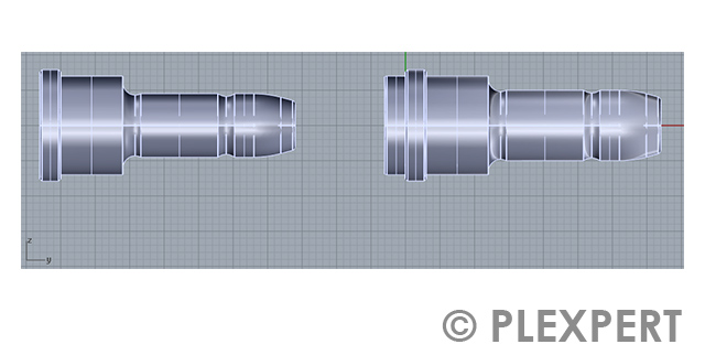
Autodesk acquired Moldflow in the year 2008. Since then, the software is known as Autodesk Moldflow.

Moldflow in Plastic Industry

Simulation: Model shown in the free viewer of the Autodesk Moldflow software.

Related topics:

Moldex3D
Cadmould
Injection Molding Simulation

This glossary of plastic industry is provided by PLEXPERT Canada Inc.

Node

A point given by x-, y- and z-coordinates in a cartesian coordinate system is named node in finite element analysis.
In a 2D or 2.5D system a node is part of a beam element or a triangle element.
In a 3D system a node is part of a tetraeder, hexaeder or a prism element.
The analysis in a FEM system is normally done from one node to his neighboring nodes.
Calculated results will be assigned to the given node.

Node in Plastic Industry

Injection Molding Simulation: One node with his x-,y-,z-coordinates.

Related topics:

Surface mesh
Volume model
Injection Molding Simulation

This glossary of plastic industry is provided by PLEXPERT Canada Inc.

Point Cloud

Geometry data is delivered as points in a cartesian coordinate system after a 2D-/3D-surface scan or a CT analysis of a part.
The sum of all points is called point cloud.
On the base of the point cloud triangle elements will be created in order to visualize the skin of the scanned object.
A return of the data into a CAD model is possible based on a point cloud as well as on the base of the generated triangle element-mesh.
It has to be noted, that the quality of the CAD surfaces show imurities.

Point Cloud in Plastic Industry

Prism

A solid, made by a parallel shift of a polygon is called prism.
In the FEM, prisms with triangular footprints are commonly used.
Its advantage is an unstructured mesh in two directions, and, at the same time, one structured main direction.
Based on the surface mesh out of triangular -elements prism- elements are extruded into the part.
Different layers of the so built prism-elements are possible. In combination with tetraeder-elements (in the remaining part), a blm mesh is built with a high accuracy and less elements. Therefore, the calculation time can be reduced.
The special form of the triangular footprint based prisms allows, in the runner system for injection molding simulation, an orientation of the fibers in flow direction inside the runner without a secondary preferred direction.

Prism in Plastic Industry

Simulation: Prisms used for the mesh of the hot runner system.

Related topics:

Fiber Orientation
Volume Model
Moldex3D

This glossary of plastic industry is provided by PLEXPERT Canada Inc.

Surface Mesh

For a 2.5D injection molding simulation a surface mesh is needed.
All surfaces of the chosen CAD model will be covered with triangle elements to build a closed mesh.
A surface mesh can be generated automatically with a CAD-System by exporting it as stl-file. This format is often used in rapid prototyping processes.
But the quality of such a mesh is not accurate enough for an injection molding simulation.
The mesh carries the geometry information and need to be optimized.
It is important to have a high amount of elements as well as to make sure that each element has a good aspect ratio.

Surface Mesh in Plastic Industry

Simulation: The prepared mesh for the usage in the next simulation.

Related topics:

Volume Model
Node
CAD

This glossary of plastic industry is provided by PLEXPERT Canada Inc.

Tetrahedron

A pyramid-like 3D-object, with 4 triangle elements is called tetrahedron (Tetrahedral Element).
In simulation tetrahedrons are used to build a volume mesh.
In a first step the surface of a part will be meshed using triangle elements.
The triangle elements will be used as a base for the first layer of tetrahedrons going into the part.
Depending on the size and orientation of the base triangle element tetrahedrons with a critical aspect ratio can be created.
The random orientation of a tetrahedron elements lead to a not preferred direction.
This can lead to longer computation times.

Tetrahedron in Plastic Industry

Simulation: A pyramid-like 3D- object - called tetrahedron (Tetrahedral Element).

Related topics:

Volume Mesh
Prism
Surface Model

This glossary of plastic industry is provided by PLEXPERT Canada Inc.

Tool Adaption

Shrinkage and warpage can be seen if plastic material is processed and cooled down in the mold and later after ejection.
In order to compensate shrinkage the mold design is modified using a factor, which is very often based on experience.
The given dimension of the part is multiplied by the factor to enlarge the part and create a cavity based on the new dimensions.
A filling simulation can be done to predict warpage due to fiber orientation, stresses, etc. as well as the shrinkage of a part during production.
In order to compensate warpage the cavity is modified in the oposite direction of what can be seen as part warpage.
This modification is called tool adaptation.
To do this in a best way the simulation result warpage is multiplied with a factor of -1 and exported as .stl file for example.
In the CAD system the mold cavity is adjusted taking care of that no undercuts are build in.
It is essential that, based on the new cavity geometry a new simulation is done in order to verify the desired results.
If this simulation shows good results the tool adaptation can be implemented into the mold.

Tool Adaption in Plastic Industry

Simulations: Left: part warpage; right: tool adaption.[/caption]

Related topics:

Reverse Engineering
Draft Angle

This glossary of plastic industry is provided by PLEXPERT Canada Inc.

Triangle Element

Three nodes in a cartesion coordinate system are used in order to create a triangle element (or short element).
Adjoining Elements share the same nodes.
The line from one node to another is called element edge.
In order to ensure a correct FEM mesh it is not allowed to have a node of an adjoining element on an element edge of another triangle element.
The sequence in which the nodes are selected determines the direction of the normal vector for the triangle element.
The normal vector defines the front side and the back side of an element.
The quality of all elements needs to be checked before a simulation can be started.

Triangle Element in Plastic Industry

Volume Model

In the CAD-System, a geometry of the part is generated.
This can be done in different ways:
One way is to use simple 3D-volumes (cylinder, cuboids, etc.) to build directly a more complex 3D-object.
The other way is to create single surfaces to build a 3D-object.
Independent of the selected way to generate the CAD model, the result is called volume model, if all surfaces build a closed skin with a clearly defined inside and outside surface.

Volume Model in Plastic Industry

Simulation: Volume model of a ship.

Related topics:

CAD
CAE
Surface Mesh

This glossary of plastic industry is provided by PLEXPERT Canada Inc.

Injection-Stretch-Blow-Molding (ISBM)

A combination of the manufacturing technologies of injection molding and stretch blow molding is the injection-stretch-blow-molding. It is used to produce hollow parts in small to medium sizes (e.g. PET bottles).
The process can be described with 5 steps:
1. Injection molding and possibly conditioning
2. Changing of cavity
3. Stretch-blow molding / Blow molding
4. Ejection of part

Injection-Stretch-Blow-Molding (ISBM) in Injection Molding

Special processes: Production of seven drug vials by injection stretch blow molding

Related topics:

Blow Molding
Turntable Mold
Extrusion

This glossary of plastic industry is provided by PLEXPERT Canada Inc.

Autarkic Temperature Control

Water is mainly used as coolant in injection molding.
It is required as cold and hot water.
If a cooling device is not connected to an external water supply, but creates cold water through an internal module, the device is called autarkic temperature control.
In this case of self-sufficient temperature control, both the water replenishment and the cooling take place independently of an on-site cooling network.

With this double benefit, a mains-independent cooling and heating process with temperatures of 20 °C to 90 °C is possible.
Higher temperatures up to 400 °C are generated electrically.

Mostly mobile, the cooling and temperature control unit can be matched in its performance to the production process and stands next to the machine(s).

Autarkic Temperature Control in Plastic Industry by ERS

Temperature Control: Autarkic temperature control with the cooling system of the type STC.

Related topics:

System Cooler
Cooling System
Heat Exchanger


This information and services are provided by:

ERS logo


This glossary of plastic industry is provided by PLEXPERT Canada Inc.

Cavity wall temperature

Particularly important for the evaluation of the temperature on the mold surface is the knowledge about the temperature on the cavity

wall.
This temperature is called cavity wall temperature.
During continous production, the cavity wall temperature is higher than the mold temperature.
The reason for this is that the hot melt is in direct contact with the cavity wall during the injection time and heats up the cavity wall.

The temperature fluctuates during a cycle due to heating (injection phase) and cooling (cooling time).
The cavity wall temperature can be determined by special sensors mounted within the cavity wall.

Cavity wall temperature in Plastic Industry by PRIAMUS

Temperature control: The mold surface temperature measured in an 8-cavity mold over time.

Related topics:

Cavity Temperature Sensor
Heat Transfer Coefficient
Thermal Impact


This information and services are provided by:

PRIAMUS logo


This glossary of plastic industry is provided by PLEXPERT Canada Inc.

Heat Exchanger

A coolant absorbs heat from the mold during the injection molding process. The transfer of the absorbed heat from one coolant to another heat transfer medium (like air, water, ...) is done by a machine named heat exchanger.
Simplified, a heat exchanger allows the transfer of thermal energy from one heat transfer medium to another.
Heat exchangers are used whenever the needed temperature of a process is above the ambient temperature.
Default temperatures for injection molding are in between 30 °C to 80 °C.

Two basic types of heat exchangers can be distinguished:

1. Water-Air:
The absorbed energy will be released to the ambient air.

2. Water-Water:
The absorbed energy will be released to a secondary water circuit.

Heat Exchanger in Plastic Industry by ERS

Temperature Control: Heat exchanger within a compression chiller

Related topics:

System Cooler
Cooling System
Quality


This information and services are provided by:

ERS logo


This glossary of plastic industry is provided by PLEXPERT Canada Inc.

Laminar Flow

The flow behavior of a fluid is described by its type of movement.
A straight forward movement in separated layers with equal temperatures is called laminar flow.
A tube with Reynolds number lower than approximately 4000 will have this kind of flow behavior.

A coolant in injection molding with laminar flow will have its highest temperature near the mold wall.
The lowest temperatures will be found in the center of the cooling channel.
The fluid is heating up from the outside to the inside.
The mold will no longer cool down as soon as the outer layer of the coolant has absorbed the maximum amount of heat.
Because of the laminar flow there is no temperature exchange within the coolant.
The outer layer of the coolant stays hot.
This means that the coolant cannot sufficiently cool the mold anymore.
Therefore, laminar flow is not recommended for a coolant.

Laminar Flow in Injection Molding

Temperature control: Laminar flow inside a cooling channel.

Related topics:

Turbulent flow
Flow Rate
Coolant Temperature

This glossary of plastic industry is provided by PLEXPERT Canada Inc.

Parallel Cooling

Like in the electrical engineering with cabels, the cooling channels in the injection mold may also have parallel connections.

There are two different possibilities to achive parallel cooling.

For the first one, the parallel connections are done directly next to the cooling device.
In order to have a flexible cooling of the mold, multiple cooling devices are needed.
However, sometimes there is only one cooling device available. In this case the flow rate of the cooling device is splitted up using a distributor block.

The second version of a parallel cooling can be found in the mold itself.
One cooling channel is split up in multiple parallel channels. Note that the same flow rate should be given through each of the channels otherwise the effectivity of the channel is reduced.
The advantage of parallel cooling is, that the channels are shorter and the starting situation is the same for each channel.
Especially for multiple cavity molds parallel cooling is a way where identical cooling can be reached for each cavity.

Parallel Cooling in Plastic Industry

Temperature control: (Picture 1): Parallel Cooling with two identical flow rates (1) and different diameters (2).
Temperature control: (Picture 2): Distribution block at the machine for a parallel cooling.

Related Topics:

Conventional Cooling
Conformal Cooling
Coolant Temperature

This glossary of plastic industry is provided by PLEXPERT Canada Inc.

Pump Curve

The task of a cooling device is to deliver coolant with a given temperature and a given flow rate into a cooling system.
Within each cooling channel there is a pressure drop. The pressure drop depends not only on the flow rate.
Furthermore length and geometry of the cooling system play an important role in the occurring pressure.
The pump curve shows the maximum flow rate at a given pressure rate.
If the pressure drop in the cooling channel is higher than suggested in the pump curve, the flow rate will drop.
As actual value the flow rate is shown, which is the maximal possible for the given pressure.
In this case the cooling channel needs to be adjusted or another cooling device should be used.

Pump Curve in Injection Molding

Temperature control: The pump curve shows, the maximum flow rate at a given back pressure.

Related topics:

Cooling System
Coolant Temperature
Reynolds Number

This glossary of plastic industry is provided by PLEXPERT Canada Inc.

Reynolds number

The flow pattern of a fluid can be defined by the dimensionless quantity called Reynoldszahl.
It is the ratio of inertial forces to viscous forces.
Calculating the Reynolds number of a fluid we need to multiply the velocity with a characteristic linear dimension and divide it by the kinematic viscosity.
The critical Reynolds number where the flow behaviour changes from laminar to turbulent flow is approximately for tubes 2300.
In the plastic industry the Reynolds number is important for the subject of the cooling system.

Reynolds number in Injection Molding

Temperature Control: Change from laminar to turbular flow

Related topics:

Flow rate
Coolant Temperature
Laminar flow

This glossary of plastic industry is provided by PLEXPERT Canada Inc.

System Cooler

The name compression chiller refers often to system cooler.
In the injection molding industry, they are used to draw the thermal energy from the coolant.
Cooling channels use the coolant with a lower temperature, for example, to regulate the flow temperature.
In a system cooler, the consumption water is actively cooled by compression.
The usual temperatures in industrial/plastic application are in between 5 °C to 25 °C.

System coolers are divided into:
1. Air cooled:
In the air-cooled version, the waste heat (condenser energy) is released into the ambient air. The advantage here is that the system cooler works independently, without on-site cooling network.
2. Water-based:
In the case of water-based chillers, the warm water is returned to an on-site water cycle (domestic water, well or river water).

System Cooler in Plastic Industry by ERS

Image 1: System cooler as small as tabletop unit type SC..K
Image 2: Temperature Control: Floor model type SC..S.

Related topics:

Conformal Cooling
Conventional Cooling
Coolant Temperature


This information and services are provided by:

ERS logo


This glossary of plastic industry is provided by PLEXPERT Canada Inc.

Turbulent Flow

The flow behavior of a fluid is described by its movement.
A vortex forward movement is called turbulent flow.
A tube with a Reynolds number higher than approximately 4000 will have this kind of flow behavior.

Because of the turbulent flow new coolant is brought to the wall of the cooling channel to take on heat.
After that it will move to the center of the cooling channel and from there back to the wall.
Due to this movement more heat can be taken by the coolant and hence the cooling is more efficient.
Therefore turbulent flow is recommended for a coolant.

Turbulent Flow in Injection Molding

Temperature control: Turbulent flow inside a cooling channel.

Related topics:

Laminar Flow
Flow Rate
Coolant Temperature

This glossary of plastic industry is provided by PLEXPERT Canada Inc.

Water tightness test

To process plastic, an injection mold must be brought to a certain temperature.
The thermal energy introduced by the melt must be dissipated to ensure that the temperature in the mold is as uniform as possible.
These tasks are performed by the temperature control system installed in the mold.
This is usually formed by bores, some of which are provided with plugs to guide the coolant (usually water).
The tightness of the individual channels in the cooling system is ideally carried out before the mold is set up.
For this purpose, water is pumped into a circuit via a pump and kept under pressure for a certain time.
If water does not leak at any point, the leak test of the sewer is complete and the next sewer can be tested.

Water tightness test in Plastic Industry

Temperature control: Simple system to perform a water tightness test
Temperature control: Tightness test in action

Related Topics:

Cooling time
Conventional cooling
Coolant temperature

This glossary of plastic industry is provided by PLEXPERT Canada Inc.