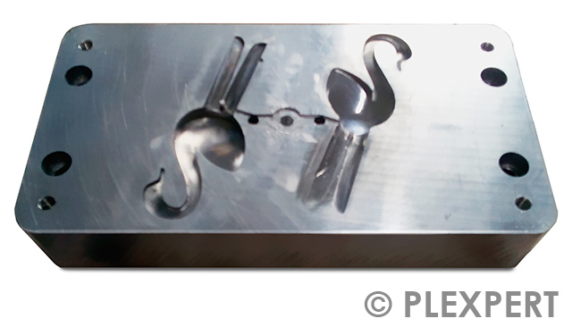
Ejection Side
A mold is usually divided into two sides according to their function.
The side with the ejector pins is called ejection side.
This side is moved for mold opening, therefore another common name is “movable side”.

Related topics:
A mold is usually divided into two sides according to their function.
The side with the ejector pins is called ejection side.
This side is moved for mold opening, therefore another common name is “movable side”.

Related topics:
To get the parts homogeneously and with as least as possible tension out of the cavity, ejectors are used.
Additional ejectors can be set as optimization for the venting system.
The ejectors are mainly axial pins, which are located on the ejector plate and fixed from the ejector holding plate.
The movement of the ejector plate takes place most of the time by hydraulic.
When moving forward, the pins press against the parts and throw them out. The backwards movement is done by hydraulic or spring force.
The movement of the ejectors has a big influence on the wear of the mold.

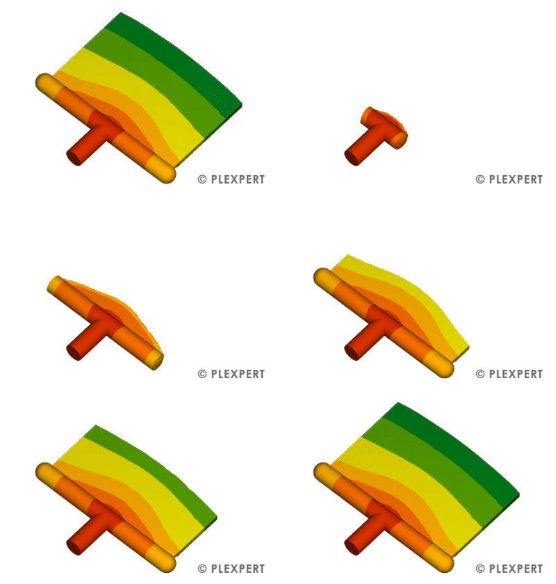
With this gate design, the plastic melt is introduced into the molded part through a widely spread cross section, allowing the flow front to expand more uniformly across a larger part width. This geometry forms the characteristic fan gate, which is particularly used for flat or thin-walled injection molded parts. The broad outlet area can reduce local shear peaks, weld lines, and visible flow marks. Width, thickness, and the transition to the part must be carefully designed because they influence pressure loss, filling behavior, part stress, and subsequent gate removal. After injection molding, the gate is usually mechanically separated from the part.

Related topics:
A mold is usually divided into two sides according to their function.
The side, which is not moving during production is called fixed side.
This side contains the runner system, therefore another common name is “injection side”.

Related topics:
A process where a physical or chemical blowing agent is solved into the polymer melt, which leads to the melt foaming and expanding in the cavity.
Due to the gas expansion of the blowing agent, the injected part will have a sandwich structure with a foamed core and compact skin layers.
The gas pressure inside the part can shorten or completely substitute the holding phase of the injection process, which leads to shorter cycle times.
With this process, part properties such as lesser warpage as well as part weight reduction can be realized. With process-optimized part design, part weight reductions and material savings of up to 35% have been realized.
Chemical blowing agents are usually added to plastics as a masterbatch and decompose into blowing gases and solid by-products under heat.
For the metering and mixing of physical blowing agents, such as nitrogen or carbon dioxide, additional equipment and a special screw are required.
Related topics:
This information and services are provided by:

Do you want to hide this popup?
The primary molding process mainly used in the plastic industry is injection molding.
With the help of the injection molding machine and the influence of heat, the plastic material is brought to a viscous state.
Subsequently, the melt is injected under pressure into the cavity in the mold.
The shape and surface structure is determined by the geometry of the cavity.
Cooling or cross-linking reaction (for elastomers) solidifies the part and it can be ejected after opening the two mold halves.
The injection molding process is particularly suitable for large quantities.
This is due to the fact of high mold costs which need to be payed proportionally by the produced parts.
Injection molded parts can be used directly after ejection.

Related topics:
A mold is usually divided into two sides according to their function.
The side with the runner system is called injection side.
This side is not moved, therefore another common name is "fixed side".

Related topics:
A mold is usually divided into two sides according to their function.
The side which is moved for mold opening is called movable side.
This side contains the ejector pins, therefore another common name is "ejection side".

A group of experts in the plastic industry founded the company PLEXPERT, 2006 in Germany, in order to save resources, providing a positive impact on budget and environment.
There are two divisions within the company. One is focusing on finite element simulations (FEM) like injection molding simulation and structural analysis.
Based on decades of practical experience DFM conform results are given by the consultant service of PLEXPERT to decrease part costs and increase quality in the production of plastic parts.
The second division is focused on the development and supply of soft- and hardware to the plastic industry. With the state of the art products PLEXPERT contributes to secure production and reduce the need of precious resources.
Today PLEXPERT has offices in Canada, Germany, Thailand and China in order to support its customers fast and effectively.
Due to a close network of plastic experts, partners are available in many other countries as well and offer PLEXPERT products and services.

PLEXPERT Company Logo.
Related topics:
For the production of injection molded parts a mold is necessary to be placed on the injection molding machine.
It is commonly build out of steel or aluminum and is designed as a permanent form.
Depending on the plastic material used millions of parts can be created with one mold.
The complexity of a mold range from a simple two-plate molds up to a complex stack mold with sliders, etc.
To avoid additional costs it is important to think about the mold concept early in the concept phase of part design.

Related topics:
To get the parts homogeneously and with as least as possible tension out of the cavity, ejectors are used.
Additional ejectors can be set as optimization for the venting system.
The ejectors are mainly axial pins, which are located on the ejector plate and fixed from the ejector holding plate.
The movement of the ejector plate takes place most of the time by hydraulic.
When moving forward, the pins press against the parts and throw them out. The backwards movement is done by hydraulic or spring force.
The movement of the ejectors has a big influence on the wear of the mold.

"Parts, which have been produced from melt by non-cutting molding (e.g. by pressing, compression molding or injection molding) in all side closed molds" are referred
to as molded parts according to DIN 7708, sheet 1 [freely translated].
Thus in injection molding, the end product, which is produced by filling the cavity with molten plastic, is called a molded part.
It should be noted that a possibly existing cold runner is not a component of the molded part.

Related topics:
The space between the two mold halves, which should be filled with melt, is called cavity.
The shrinkage of the material needs to be considered for the production of the cavity to get dimensionally accurate parts.
In the injection molding simulation, it is important to use the cavity size for the warpage calculation.

The cavity contains air, which is pushed out by the arriving melt.
Therefore, venting is necessary to allow the air to escape the cavity.
Otherwise a compression of the air occurs, which leads to a rise of the temperature (burn mark).
The venting consists of small gaps, which are situated for example at the parting line, at the sliders and at the ejector pins.
Depending on the used polymer, the height of the gap needs to be adjusted.
If the gap is too small, it prevents the air from escaping.
If the gap is too big, flash formation occurs at the part.

The pressure at different positions inside the cavity/runner is called “Pressure Distribution”.
Ideally in injection molding process, the pressure distribution should be uniform throughout the cavity after the molten plastic completely fills the cavity. In this case the molded part shrinks uniformly.
In reality due to the different cooling behaviour of the part there is always a difference in pressure distribution.
Injection molding simulation is a great tool to predict the pressure inside the cavity, which can help to achieve uniform pressure distribution as good as possible.
With this gate design, the plastic melt is introduced into the molded part through a widely spread cross section, allowing the flow front to expand more uniformly across a larger part width. This geometry forms the characteristic fan gate, which is particularly used for flat or thin-walled injection molded parts. The broad outlet area can reduce local shear peaks, weld lines, and visible flow marks. Width, thickness, and the transition to the part must be carefully designed because they influence pressure loss, filling behavior, part stress, and subsequent gate removal. After injection molding, the gate is usually mechanically separated from the part.

Related topics:
When at least two melt fronts meet, a weld line occurs.
Weld lines display on one hand a reduction of the mechanical strength, on the other hand a beauty error in the part.
The lower the melt front temperatures, the more difficult it is for the melt fronts to merge.
The smaller the meeting angle (melt fronts meet head-on), the more critical.
For fiber filled materials, a weld line changes the orientation of the fibers, that they will orient perpendicular to the flow direction.
To reduce weld lines it is possible to work with sequential injection or overflow cavities.

Related topics:
With this gate design, the plastic melt is guided into the molded part through a very wide and relatively thin entry cross section, allowing the flow front to spread uniformly along the edge of the component. This geometry, known as a film gate, is often used for flat, thin-walled, or visually demanding injection molded parts where highly homogeneous mold filling is required. The broad melt entry can reduce local shear loads, pressure peaks, and visible flow marks. The design of the width, thickness, and transition to the part has a major influence on filling behavior, part stress, packing pressure effectiveness, and subsequent gate removal. After injection molding, the gate is usually separated from the part mechanically or by post-processing.

Related topics:
A mold is usually divided into two sides according to their function.
The side, which is not moving during production is called fixed side.
This side contains the runner system, therefore another common name is "injection side".

Related topics:
All melt channels together are called runner or runner system.
For these names, there is no distinction between hot and cold runner.
A good runner is responsible for a balanced filling of the cavity and less material and pressure loss.

Related topics:
The injection molding machine can be separated into different units.
At the beginning of the injection molding process stands the injection unit.
It contains the hopper, through which the granule rinses inside the cylinder with the screw.
The rotating screw and the heating rods at the outside of the cylinder cause the melting and homogenization of the plastic while the meld is transferred to the tip of the screw.
Here the plastic is metered for the process.
At the end of the injection unit is a nozzle through which the melt is pushed into the mold by the forward moving screw during during injection.

Related topics:
A process where a physical or chemical blowing agent is solved into the polymer melt, which leads to the melt foaming and expanding in the cavity.
Due to the gas expansion of the blowing agent, the injected part will have a sandwich structure with a foamed core and compact skin layers.
The gas pressure inside the part can shorten or completely substitute the holding phase of the injection process, which leads to shorter cycle times.
With this process, part properties such as lesser warpage as well as part weight reduction can be realized. With process-optimized part design, part weight reductions and material savings of up to 35% have been realized.
Chemical blowing agents are usually added to plastics as a masterbatch and decompose into blowing gases and solid by-products under heat.
For the metering and mixing of physical blowing agents, such as nitrogen or carbon dioxide, additional equipment and a special screw are required.
Related topics:
This information and services are provided by:

It is important in the plastic industry to reduce the residual moisture of the plastic granulate.
Therefore most of the plastics need a material drying before processing.
In the hot air or vacuum dryer the residual moisture is reduced.
It should be noticed, that each plastic needs different temperatures and times for the drying to reach a minimal residual moisture, while the material is not going brittle.

Related topics:
The pressure inside the cavity is called cavity pressure. It is usually smaller than the specific pressure due to pressure losses.
Sensors inside the mold are used to measure the cavity pressure and to compare it with the injection molding simulation.
The time-pressure curve of a complete cycle helps to validate the vp-switch, as well as the effect of the packing phase.
The part quality can be evaluated easier.

Plastic additives as pellets, which are added to the natural raw polymer to dye or to change the properties, are called Masterbatch.
They have a higher amount of colorants or additives than the raw polymer.
It is to be noted, which substrate is used (mainly PE or PA).
Masterbatches are easy to handle and provide a better process reliability than powder additives.
There are additive masterbatches (e.g. flamability or UV-stabilization), color masterbatches (to dye) and combination masterbatches (dyes and additives).
A small percentage of the masterbatch is enough for an intensive dyeing.

Chemical connections of monomers are called polymers.
They are macromolecules with the same inner structure.
Dependent on the amount of monomer types, polymers can be devided into homopolymers (one type of monomers), copolymer (multiple types of monomers) and polymerblends (multiple homopolymers and/or multiple copolymers).

Related topics:
The injection molding process contains different stages:
After the injection time (1), the packing time (2) and residual cooling time (3) follow.
The cycle will be completed with the mold movement (open, eject and closing) (4).
When all stages passed one time it is called a cycle and the process starts again.

Related Topics:
A geometrical difference between target and actual geometry is called warpage.
In the plastic industry this is caused by the developing stresses during the process.
Stresses arise due to the different shrinkage degrees in the part.
Varying Cooling rates, Orientation of the molecules, in-mold constraints (limitations for the shrinkage), uneven wall thickness/packing pressure are responsible for the differences.
These effects can cancel each other out or enhance one another.